FordParts
My Garage
My Account
Cart
OEM 2000 Ford Crown Victoria Clock Spring
Spiral Cable Clock Spring- Select Vehicle by Model
- Select Vehicle by VIN
Select Vehicle by Model
orMake
Model
Year
Select Vehicle by VIN
For the most accurate results, select vehicle by your VIN (Vehicle Identification Number).
1 Clock Spring found


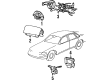
2000 Ford Crown Victoria Clockspring Part Number: F8AZ-14A664-AA
Product Specifications- Other Name: Cover And Contact Plate Assembly; Air Bag Clockspring
- Manufacturer Note: #F8AC 14A664-AA, screw-mounted
- Base No.: 14A664
- Item Weight: 0.70 Pounds
- Item Dimensions: 6.1 x 6.1 x 2.9 inches
- Condition: New
- Fitment Type: Direct Replacement
- SKU: F8AZ-14A664-AA
- Warranty: This genuine part is guaranteed by Ford's factory warranty.
2000 Ford Crown Victoria Clock Spring
If you're seeking quality and affordability, look no further than our extensive inventory of genuine 2000 Ford Crown Victoria Clock Spring available at FordPartsDeal.com. You can confidently purchase our OEM 2000 Ford Crown Victoria Clock Spring as they are supported by the manufacturer's warranty and our hassle-free return policy, alongside the benefit of our fast delivery service.
2000 Ford Crown Victoria Clock Spring Parts Q&A
- Q: What Precautions Should Be Taken When Servicing the Clock Spring on 2000 Ford Crown Victoria?A: Wear safety glasses and be careful with the module when servicing the air bag sliding contact. Always disconnect battery when making repairs, always check sensors and damaged trim covers should be replaced. Removal and installation of components must be done as per the correct steps and all connections properly fixed. Discard diagnostic tools prior to using the roads to make sure things are safe.
Related 2000 Ford Crown Victoria Parts
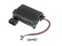 2000 Ford Crown Victoria Fuse Box
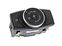 2000 Ford Crown Victoria Headlight Switch
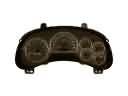 2000 Ford Crown Victoria Instrument Cluster
 2000 Ford Crown Victoria Air Bag
 2000 Ford Crown Victoria Air Bag Control Module
 2000 Ford Crown Victoria Air Bag Sensor
 2000 Ford Crown Victoria Brake Light Switch
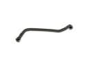 2000 Ford Crown Victoria Crankcase Breather Hose
 2000 Ford Crown Victoria Mirror Switch
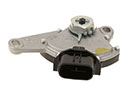 2000 Ford Crown Victoria Neutral Safety Switch
 2000 Ford Crown Victoria Spark Plug
 2000 Ford Crown Victoria Vehicle Speed Sensor