
Popular OEM Mercury Parts
- Body & Hardware Parts View More >
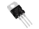
- Electrical Parts View More >
- Interior & Exterior Trim Parts View More >
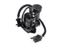
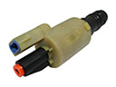
- Air & Fuel Delivery Parts View More >
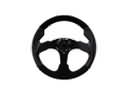
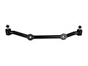
- Steering Parts View More >
- Emission Control & Exhaust Parts View More >
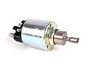
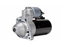
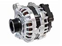
- Charging & Starting Parts View More >
- Engine Parts View More >
- Belts & Cooling Parts View More >
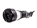
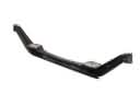
- Suspension Parts View More >
- Brakes Parts View More >
- A/C & Heating Parts View More >


Why Buy Genuine Mercury Parts From FordPartsDeal.com
FordPartsDeal.com is a reliable source to buy genuine Mercury parts, including Headlights & Lighting that add a special touch of care to your vehicle. If you are looking to buy new Mercury parts, such as Transmission, we feature parts with manufacturer standards, so specifications match what your vehicle was built with. Our team uses highly trusted components to support optimal fit and durability, helping parts install cleanly and perform as designed. Choosing authentic Mercury components reduces the chance of rework and protects system performance over time, because dimensions, materials and validation follow factory criteria. From fasteners to larger assemblies, the emphasis stays on correct form and function rather than substitutes that may vary. That consistent factory-spec standard is why many Mercury owners choose FordPartsDeal.com when quality and fit are paramount. Select genuine parts with confidence and keep your vehicle aligned with factory intent.
FordPartsDeal.com offers unbeatable quality without breaking your wallet. FordPartsDeal.com is proud to deliver a wide array of genuine discounted parts to fit your needs at prices lower than wholesale. Shopping is stress-free for OEM Mercury parts, like Driveline & Axles: our online catalog helps you locate exactly what you need and the VIN checker confirms accuracy before you order. Our team of specialists provides friendly, trustworthy service across all Mercury parts categories. We are also distributed through many warehouses that ship quickly and our fulfillment system operates efficiently to deliver in-stock items without unnecessary delays. Returns are easy if plans change, keeping the process simple from cart to doorstep. By combining cost savings with clear tools and responsive support, FordPartsDeal.com helps keep your project moving forward while staying on budget.
Mercury began in 1938 and introduced cars in 1939. Mercury made mid-sized cars that were constructed with a softer ride and sharp styling. Mercury took its name from the Roman messenger god, giving it a memorable label. Mercury took on a self-identity with its showrooms and retained attributes such as finer suspension and spacious cabins. Mercury provided better interiors to reduce road noise and easy control. Mercury had established such popular models as the Cougar and the Grand Marquis. Throughout the decades, Mercury continued to announce novelties in terms of comfort and basic technologies. Mercury stopped making cars in early 2011. Mercury made strong efforts to maintain balance between feel and value.
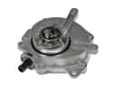
Mercury's composed performance relies on stable hydraulics, clean fueling and disciplined torque transfer. The genuine Mercury transmission pan keeps fluid sealed and temperatures steady. Clutch packs bite cleanly and shift timing stays crisp. Mercury fuel delivery brings quiet starts and even throttle. Pair an OEM Mercury fuel pump parts with a genuine Mercury fuel rail pressure sensor to hold rail pressure under load or altitude change. That smooths tip-in, supports emissions control, and keeps warning lights off. A Mercury torque converter manages coupling without shudder. Launches are simple and low-speed maneuvers are accurate. Bearings run cooler. All Mercury parts are designed to meet Mercury NVH targets and dimensions. Fit is exact and sealing surfaces seat the first time. Installs finish without rework. The result is steadier response, lower cabin noise, and durability that protects Mercury refinement and long-term value.
Mercury Parts and Q&A
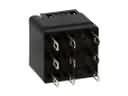
- Q: How to service and repair the ignition coil on Mercury Cougar?A:To service and replace ignition coil, begin by removing electrical connector of the ignition coil on one side and on the other side spark plug wire. Next take out the bolts attaching the ignition coil. To uninstall, just do these in-reverse.
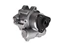
- Q: How to install the power steering pump on Mercury Grand Marquis?A:Installation of the power steering pump follows the same process in reverse with the exception of replacing any seal rings required. After installation, fill the system and leak test the system to make sure that it works properly.
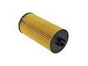
- Q: How to service a cartridge type oil filter on Mercury Mariner?A:In order to service the cartridge oil filter, one has to place the vehicle in neutral. Loose oil filter cover and drain plug to drain oil. Dispose of old parts, grease surfaces and lubricate new O-rings. Fit the new filter and cover, tightening to the required torque and ensure that you replace the drain plug.


