FordParts
My Garage
My Account
Cart
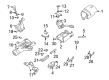
OEM 2000 Ford F-250 Super Duty Turn Signal Switch
Turn Signal Indicator Switch- Select Vehicle by Model
- Select Vehicle by VIN
Select Vehicle by Model
orMake
Model
Year
Select Vehicle by VIN
For the most accurate results, select vehicle by your VIN (Vehicle Identification Number).
1 Turn Signal Switch found


 Product Specifications
- Other Name: Switch Assembly - Direction Indicator; Turn Signal & Combination Lever; Hazard Flasher; Multi-Function Switch.; Turn Signal & Hazard Switch
- Replaces: YL3Z-13K359-CA
- Base No.: 13K359
- Item Weight: 1.10 Pounds
- Item Dimensions: 10.6 x 4.6 x 6.1 inches
- Condition: New
- Fitment Type: Direct Replacement
- SKU: Y85Z-13K359-CA
- Warranty: This genuine part is guaranteed by Ford's factory warranty.
2000 Ford F-250 Super Duty Turn Signal Switch
If you're seeking quality and affordability, look no further than our extensive inventory of genuine 2000 Ford F-250 Super Duty Turn Signal Switch available at FordPartsDeal.com. You can confidently purchase our OEM 2000 Ford F-250 Super Duty Turn Signal Switch as they are supported by the manufacturer's warranty and our hassle-free return policy, alongside the benefit of our fast delivery service.
2000 Ford F-250 Super Duty Turn Signal Switch Parts Q&A
- Q: How to service and repair the turn signal switch on 2000 Ford F-250 Super Duty?A: The procedure for servicing and fixing the turn signal switch starts by extracting the ignition switch lock cylinder. Use this lock cylinder key to enter and turn it into the ignition switch RUN position. A punch tool must be used to trigger the ignition switch lock cylinder release button when withdrawing the ignition switch lock cylinder. The direction for removal includes twisting the tilt wheel handle as well as the shank. Steer clear of the upper and lower steering column shrouds by extracting their screws. Users must unscrew the multifunction switch while disconnecting its electrical connectors before extracting the switch from further use. Installation will be finished through opposite methods to strip down removal procedures.
Related 2000 Ford F-250 Super Duty Parts
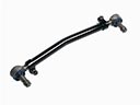 2000 Ford F-250 Super Duty Drag Link
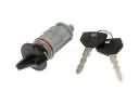 2000 Ford F-250 Super Duty Ignition Lock Cylinder
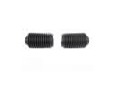 2000 Ford F-250 Super Duty Rack And Pinion
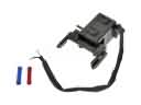 2000 Ford F-250 Super Duty Shift Interlock Solenoid
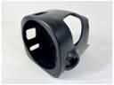 2000 Ford F-250 Super Duty Steering Column Cover
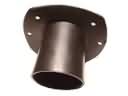 2000 Ford F-250 Super Duty Steering Column Seal
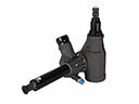 2000 Ford F-250 Super Duty Steering Gear Box
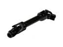 2000 Ford F-250 Super Duty Steering Shaft
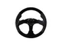 2000 Ford F-250 Super Duty Steering Wheel
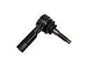 2000 Ford F-250 Super Duty Tie Rod
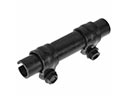 2000 Ford F-250 Super Duty Tie Rod Adjusting Sleeve
 2000 Ford F-250 Super Duty Upper Steering Column Bearing