
Popular OEM Ford F-250 Super Duty Parts
- Body & Hardware Parts View More >
- Electrical Parts View More >
- Interior & Exterior Trim Parts View More >
- Air & Fuel Delivery Parts View More >
- Steering Parts View More >
- Emission Control & Exhaust Parts View More >
- Charging & Starting Parts View More >
- Engine Parts View More >
- Belts & Cooling Parts View More >
- Suspension Parts View More >
- Brakes Parts View More >
- A/C & Heating Parts View More >


Why Buy Genuine Ford F-250 Super Duty Parts From FordPartsDeal.com
FordPartsDeal.com offers a smart and convenient way to buy genuine parts online. We sell new OEM Ford F-250 Super Duty parts, including Headlights & Lighting. Authorized dealers directly provide all the Ford F-250 Super Duty parts and assemblies to ensure the optimal quality and fit. We also provide all properly fitting Ford F-250 Super Duty parts, such as Transmission, Driveline & Axles specific to your model. When you shop here, you get real Ford value at highly competitive prices. All our products come with the same Ford warranty available at other dealerships. Our easy-to-use catalog helps you quickly identify the right part for your car. You'll receive fast shipping from our warehouse network, keeping your Ford F-250 Super Duty running smoothly. Our staff consists of Ford professionals who are ready to assist you. We aim to treat each customer as if they were stepping out of a Ford showroom. VIN verification and our live support ensure that the part you order is the right Ford F-250 Super Duty part for your vehicle.
The Ford F-250 Super Duty made its debut in 1999 as the key development in the Ford F-Series which specialized for towing heavy loads and commercial business tasks. Equipped with a 5.4-liter V8 engine as well as the 4R100 transmission the Ford F-250 Super Duty achieved a maximum payload of 4,930 pounds. The GVWR of Ford F-250 models fell between 8,800 and 10,000 pounds based on selected packages. Engineered features of the F-250 Super Duty include its heavy-duty chassis structure and its robust suspension framework with big axles because this design accommodates personal and business uses. The second-generation model of PowerStroke V8 diesel engine integrated 6.4-liter piezoelectric injectors alongside sequential turbochargers to achieve performance excellence with efficient operation. The Ford F-250 integrated a six-speed automatic transmission that came standard with the 4x2 and optional 4x4 wheel configurations thus improving both performance and off-road potential. The F-250 Super Duty's improved interior design includes features that improve control functionality along with more comfortable conditions. The vehicle grew physically while receiving updated grille designs but maintained its sequential two-wheel I-beam steering system. Real Ford F-250 Super Duty parts provide peak performance together with extended durability under manufacturer warranty protection.
Ford F-250 Super Duty groups these issues by engine cooling, emissions control, and intake boost delivery. Cooling concerns include radiator leaks and rapid level loss. A faulty bypass inside the thermostat assembly can spike system pressure. Replace the thermostat assembly and radiator, then bleed air and pressure test. The F-250 Super Duty may show sweet odors and steam at idle. Emissions control problems can produce white exhaust smoke during acceleration. An EGR cooler leak feeds coolant into the intake stream. Service the system and replace the EGR valve, then refill and verify cleanliness. Ford F-250 Super Duty drivability complaints often involve lost power under load. The turbocharger to intake manifold hose can slip off its seat. Refit the hose, install improved clamps, and check for oil contamination. Inspect turbo outlet geometry and secure all connections. Verify clamps are aligned and torque matches service specifications. A boost leak test confirms recovery on the F-250 Super Duty. Ford F-250 Super Duty should be monitored for temperatures and warnings after repairs. Ford F-250 Super Duty maintenance also benefits from fresh coolant and correct cap ratings.
Ford F-250 Super Duty Parts and Q&A
- Q: How to service and repair the steering wheel on Ford F-250 Super Duty?A:In order to remove the steering wheel, dismantle the driver airbag module, then straighten the wheel and dispose of the bolt. Use a new bolt with tightening of 40 Nm (30 lb-ft). Clock Spring To maintain no rotation to the tape, then invert removal steps by re-seating the steering wheel.
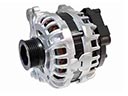
- Q: How to service and repair the alternator on Ford F-250 Super Duty?A:In order to service the alternator, disconnect the battery and remove the drive belt. To prevent cross-threading, hand start the generator battery positive cable nut. Unplug the electrical connectors and wire harness and pull off the generator bracket and low bolts. To install it, follow the reversal of the steps of removal.
- Q: How to service and repair the catalytic converter on gasoline engines on Ford F-250 Super Duty?A:In order to fix the catalytic converter, place the vehicle in neutral in a hoist. Take out the Y-pipe flange nuts and gasket, unscrew the converter and put in a new one (unless it is not needed). Apply anti-seize to sensor, clean surfaces and tighten all connections to required torque values.


