FordParts
My Garage
My Account
Cart
OEM 2000 Ford F-350 Super Duty Clutch Master Cylinder
- Select Vehicle by Model
- Select Vehicle by VIN
Select Vehicle by Model
orMake
Model
Year
Select Vehicle by VIN
For the most accurate results, select vehicle by your VIN (Vehicle Identification Number).
1 Clutch Master Cylinder found


2000 Ford F-350 Super Duty Master Cylinder Part Number: F81Z-7A543-FA
$63.47 MSRP: $97.50You Save: $34.03 (35%)Ships in 1-2 Business DaysProduct Specifications- Other Name: Master Cylinder Assembly; Clutch Master Cylinder; Brake Master Cylinder
- Base No.: 7A543
- Item Weight: 1.00 Pounds
- Item Dimensions: 9.2 x 8.2 x 3.0 inches
- Condition: New
- Fitment Type: Direct Replacement
- SKU: F81Z-7A543-FA
- Warranty: This genuine part is guaranteed by Ford's factory warranty.
2000 Ford F-350 Super Duty Clutch Master Cylinder
If you're seeking quality and affordability, look no further than our extensive inventory of genuine 2000 Ford F-350 Super Duty Clutch Master Cylinder available at FordPartsDeal.com. You can confidently purchase our OEM 2000 Ford F-350 Super Duty Clutch Master Cylinder as they are supported by the manufacturer's warranty and our hassle-free return policy, alongside the benefit of our fast delivery service.
2000 Ford F-350 Super Duty Clutch Master Cylinder Parts Q&A
- Q: How to service and repair the clutch master cylinder on 2000 Ford F-350 Super Duty?A: A new clutch master cylinder assembly requires complete removal of the clutch hydraulic system as a unit during service or repair operations. First disconnect the clutch hydraulic tube from its dash clip position before raising and supporting the vehicle to unlock and remove the slave cylinder from the transmission by twisting and compressing it for removal. The clutch hydraulic tube should be detached from the floor pan clip so that the slave cylinder and hydraulic tube can be positioned forward beneath the left engine bank to decrease hydraulic tube tension. To detach the clutch master cylinder push rod from the clutch pedal users should lower their vehicle while unlocking the push rod bushing retaining clips and remove the push rod bushing. The technician must separate the clutch master cylinder push rod by removing both the switch cover along with the pedal position switch (7C534). The technician separates the power distribution box from its bracket before removing the clutch master cylinder by clockwise twisting and compressing it 45 degrees. Take the clutch hydraulic reservoir from the wiring tray while you disconnect the clutch hydraulic tube from the brake master cylinder assembly so place the reservoir nearby. Before hydraulic tube separation clean all clutch system components while placing a suitable container under the clutch master cylinder. Drive out the roll pin by using a 3/32-inch punch before you discard it while also disconnecting the hydraulic tube from the clutch master cylinder. Take out all residual O-rings from the clutch master cylinder before putting a cap on the exposed hydraulic tube end. The new push rod needs installation in the clutch master cylinder following hydraulic component support by placing the reservoir above the master cylinder. Use Ford High Performance DOT 3 Motor Vehicle Brake Fluid C6AZ-19542-AB or equivalent meeting Ford specification ESA-M6C25-A to purges the assembly from air. Repeat the fluid filling process until air elimination is complete. Secure both ends of the hydraulic tube by installing a new roll pin to attach a new O-ring seal that needs DOT 3 Brake Fluid for lubrication. Bleed the clutch hydraulic system by bench method and move the system into the vehicle while routing the hydraulic tube properly and attaching the clutch hydraulic reservoir to the wiring tray. To install the clutch master cylinder secure the hydraulic tube counterclockwise by 45 degrees in a twisting motion while compressing it. This action locks the clutch pedal and support bracket together but also positions the rubber seal against the bulkhead. Move the hydraulic tube beneath the brake booster reservoir before reconnecting the power distribution box with its bracket. Position the clutch pedal position switch on the clutch master cylinder push rod and position its flat side toward the tab and set the switch wiring connector at 12 o'clock before securing it with the switch cover. Locate the new push rod bushing then connect the clutch master cylinder push rod to the clutch pedal while handling it gently since the pedal will be under spring tension. Elevate the vehicle while properly directing hydraulic tubing and slave cylinder towards the transmission before tightening the slave cylinder into place on the transmission. Lower the vehicle when you connect both ends of the clutch hydraulic tube first to the floor pan clip and then to the dash clip. Pull the clutch pedal to insert the push rod into the clutch master cylinder before testing the system functionality.
Related 2000 Ford F-350 Super Duty Parts
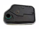 2000 Ford F-350 Super Duty Automatic Transmission Filter
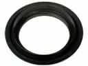 2000 Ford F-350 Super Duty Automatic Transmission Seal
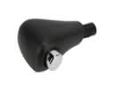 2000 Ford F-350 Super Duty Automatic Transmission Shift Levers
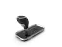 2000 Ford F-350 Super Duty Automatic Transmission Shifter
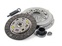 2000 Ford F-350 Super Duty Clutch Disc
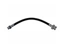 2000 Ford F-350 Super Duty Clutch Hose
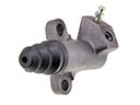 2000 Ford F-350 Super Duty Clutch Slave Cylinder
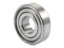 2000 Ford F-350 Super Duty Pilot Bearing
 2000 Ford F-350 Super Duty Torque Converter
 2000 Ford F-350 Super Duty Transfer Case
 2000 Ford F-350 Super Duty Transmission Assembly
 2000 Ford F-350 Super Duty Transmission Pan