FordParts
My Garage
My Account
Cart
OEM 2000 Lincoln Town Car Clock Spring
Spiral Cable Clock Spring- Select Vehicle by Model
- Select Vehicle by VIN
Select Vehicle by Model
orMake
Model
Year
Select Vehicle by VIN
For the most accurate results, select vehicle by your VIN (Vehicle Identification Number).
1 Clock Spring found


2000 Lincoln Town Car Clockspring Part Number: XW1Z-14A664-AA
Product Specifications- Other Name: Cover And Contact Plate Assembly; Air Bag Clockspring
- Replaces: F8VZ-14A664-AA
- Base No.: 14A664
- Item Weight: 0.80 Pounds
- Item Dimensions: 6.0 x 3.0 x 6.1 inches
- Condition: New
- Fitment Type: Direct Replacement
- SKU: XW1Z-14A664-AA
- Warranty: This genuine part is guaranteed by Ford's factory warranty.
2000 Lincoln Town Car Clock Spring
If you're seeking quality and affordability, look no further than our extensive inventory of genuine 2000 Lincoln Town Car Clock Spring available at FordPartsDeal.com. You can confidently purchase our OEM 2000 Lincoln Town Car Clock Spring as they are supported by the manufacturer's warranty and our hassle-free return policy, alongside the benefit of our fast delivery service.
2000 Lincoln Town Car Clock Spring Parts Q&A
- Q: How Should One Service the Clock Spring for Safe and Proper Installation on 2000 Lincoln Town Car?A: Wear protective safety glasses before handling the air bag sliding contact to protect yourself from injuries that might occur in case of accidental deployment. You should handle active air bag modules with their air bag and trim cover facing away from your body and they must never be placed with the trim cover pointing downwards. Use soap water for hand washing right after deployment to wipe off sodium hydroxide particles from your skin. Prevent air bag deployment by never probing the connectors of the air bag module. Customers should obtain new air bag modules instead of repainting trim covers because they show discoloration or have damage. Perform a correct angular alignment check on the air bag supplemental restraint system sensors during an inspection of the sensor mounting structure and wiring connector to replace any damaged parts. The back up power supply requires depletion through disconnecting the battery ground cable and waiting at least one minute and disconnecting any auxiliary batteries or power supply if installed. Start the replacement by cutting off the battery ground cable then removing the steering wheel with the driver air bag module followed by ensuring straight wheel positioning. After taping two strips of masking tape to block the air bag sliding contact you should set the steering column at its full down tilt position prior to removing both the wheel handle and shank. Begin by unscrewing the two bolts which secure the lower steering column cover then set the parking brake release in a strategic position. The next step requires removal of five bolts to separate the lower steering column reinforcement. This procedure must be followed by removing four screws from the lower steering column shroud. To remove the ignition switch lock cylinder you should push up on its release tab when it is in RUN position so you can remove it by pulling outward. The instrument panel lower insulator installation follows by disconnecting the transmission range indicator cable while unscrewing the forward steering column mounting nuts and the aft steering column mounting nuts in order for the steering column to drop enough to remove the upper steering column shroud. Remove the voice-activated cellular phone microphone through the retaining tab depression followed by the removal of the Passive Anti-theft System (PATS) transmitter with its retaining screw. Start by removing the key-in-ignition warning indicator switch before disconnecting the air bag sliding contact electrical connectors through tie strap cutting and wire separation from the wiring harness retainer and finally removing the connectors from their wire connector bracket. The retaining clips of the air bag sliding contact must be pried loose so the sliding contact can be removed. Install the new air bag sliding contact on the steering column through the retaining clip engagement before you connect the electrical connectors into the wire connector bracket while securing wires in wiring harness retainer with a new tie strap. Follow installation of the key-in-ignition warning indicator switch together with the PATS transmitter as well as its retaining screw and the voice-activated cellular phone microphone if present. After installing the upper steering column shroud you must position the ignition switch lock cylinder correctly before testing its functionality. Position the steering column upward and hand-tighten its forward mounting nuts yet install the transmission range indicator cable before tightening both rearward and forward steering column mounting nuts. Position the parking brake release properly during installation of the lower steering column shroud along with its reinforcement and cover. The last installation task includes the tilt wheel handle and shank together with the removal of masking tape from the air bag sliding contact followed by steering wheel attachment and driver air bag module placement.
Related 2000 Lincoln Town Car Parts
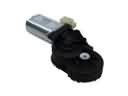 2000 Lincoln Town Car Seat Motor
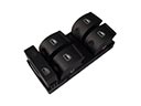 2000 Lincoln Town Car Window Switch
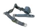 2000 Lincoln Town Car Seat Belt
 2000 Lincoln Town Car Air Bag
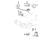
 2000 Lincoln Town Car Air Bag Control Module
 2000 Lincoln Town Car Air Bag Sensor
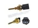 2000 Lincoln Town Car Cylinder Head Temperature Sensor
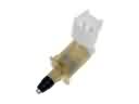 2000 Lincoln Town Car Door Jamb Switch
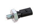 2000 Lincoln Town Car Oil Pressure Switch
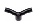 2000 Lincoln Town Car PCV Valve Hose
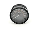 2000 Lincoln Town Car Speedometer
 2000 Lincoln Town Car Speedometer Cable