FordParts
My Garage
My Account
Cart
OEM 2001 Ford Focus Clutch Master Cylinder
- Select Vehicle by Model
- Select Vehicle by VIN
Select Vehicle by Model
orMake
Model
Year
Select Vehicle by VIN
For the most accurate results, select vehicle by your VIN (Vehicle Identification Number).
1 Clutch Master Cylinder found


2001 Ford Focus Master Cylinder Part Number: 1M5Z-7A543-AA
$50.10 MSRP: $71.67You Save: $21.57 (31%)Ships in 1-3 Business DaysProduct Specifications- Other Name: Master Cylinder Assembly; Clutch Master Cylinder; Brake Master Cylinder
- Manufacturer Note: ALL; MTX-75, IB5 and SVT w/Getrag 285 6-spd
- Replaces: YS4Z-7A543-AA
- Base No.: 7A543
- Item Weight: 0.90 Pounds
- Item Dimensions: 8.2 x 6.1 x 4.6 inches
- Condition: New
- Fitment Type: Direct Replacement
- SKU: 1M5Z-7A543-AA
- Warranty: This genuine part is guaranteed by Ford's factory warranty.
2001 Ford Focus Clutch Master Cylinder
If you're seeking quality and affordability, look no further than our extensive inventory of genuine 2001 Ford Focus Clutch Master Cylinder available at FordPartsDeal.com. You can confidently purchase our OEM 2001 Ford Focus Clutch Master Cylinder as they are supported by the manufacturer's warranty and our hassle-free return policy, alongside the benefit of our fast delivery service.
2001 Ford Focus Clutch Master Cylinder Parts Q&A
- Q: How to service and repair the clutch master cylinder on 2001 Ford Focus?A: The first step for clutch master cylinder service consists of removing the battery ground cable. Be mindful when working to avoid brake fluid touching paint since immediate rinsing with cold water helps in such cases. Insert a proper syringe into the reservoir to drain the brake fluid until the MIN mark appears and replace the cap. The first step includes removing the air cleaner followed by disconnecting the Central Junction Box (CJB) through removing its retaining bolt and unclipping the box. Close the fluid supply lines of the clutch master cylinder and slave cylinder using caps as a preventive measure against fluid leakage or dirt contamination before you disconnect these lines with a thin bladed screwdriver tool and remove the clips. To remove the instrument panel lower panel users will need to take out the screws and free the fastener until the panel becomes fully detachable. During this process they should disconnect the Data Link Connector (DLC) along with the hood release cable. Detach the supply line of the clutch slave cylinder from the front bulkhead before removing the clip. The pedal assembly first requires disconnecting the electrical connectors of the starter safety switch, speed control deactivation switch, stop lamp switch, and clutch position switch and disconnecting the brake pedal actuating rod retaining pin by depressing its locking tang. The complete pedal assembly needs full removal to expose the clutch master cylinder retainer bolts before you can disassemble the master cylinder by placing the pedal assembly in a vise and removing bolts from the master cylinder then sliding out the pedal arm actuating rod. The actuating rod should connect to the pedal arm followed by clutch master cylinder installation onto the pedal assembly before reinstalling it in the vehicle. After securing the brake pedal actuating rod retaining pin through locking its position the locking tab must be visible before tightening the retaining nuts. The front bulkhead gets the clutch slave cylinder supply line installation along with its clip placement. Measure the extended length of the three necessary plungers: the speed control deactivation switch needs to measure 24 mm and the stop lamp switch needs to measure 21 mm and the starter safety switch needs to measure 26 mm. Install the switches by turning the stop lamp switch opposite to the direction of the other switches to stop binding. The installation of switches should start with the speed control deactivation switch (green) followed by stop lamp switch (grey) then clutch position switch (red) and finish with starter safety switch (black). The connection of electrical wires to the switches must be followed by setting the starter safety switch through clutch pedal operation. Reinstall new O-ring seals before you attach the fluid supply lines to both the clutch master cylinder and slave cylinder by setting the clips properly in place. The hood release cable joins with the Data Link Connector (DLC) to the instrument panel lower panel before securing the panel trim through screw and fastener installation. Reinstall the Central Junction Box by installing its retaining bolt and attaching the clip then reinstall the air cleaner. Bleeding of the hydraulic clutch system should follow the completion of adding brake fluid up to the mark with Super DOT 3. Reconnecting the ground cable to the battery finishes the repair.
Related 2001 Ford Focus Parts
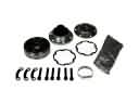 2001 Ford Focus CV Joint
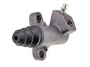 2001 Ford Focus Clutch Slave Cylinder
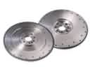 2001 Ford Focus Flywheel
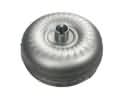 2001 Ford Focus Torque Converter
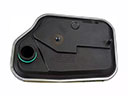 2001 Ford Focus Automatic Transmission Filter
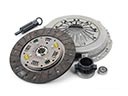 2001 Ford Focus Clutch Disc
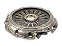 2001 Ford Focus Pressure Plate
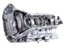 2001 Ford Focus Transmission Assembly
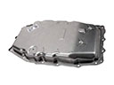 2001 Ford Focus Transmission Pan