FordParts
My Garage
My Account
Cart
OEM 2001 Lincoln Town Car Intake Manifold
Engine Intake Manifold- Select Vehicle by Model
- Select Vehicle by VIN
Select Vehicle by Model
orMake
Model
Year
Select Vehicle by VIN
For the most accurate results, select vehicle by your VIN (Vehicle Identification Number).
1 Intake Manifold found


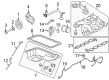
2001 Lincoln Town Car Intake Manifold Part Number: 3W7Z-9424-AE
$334.83 MSRP: $491.67You Save: $156.84 (32%)Product Specifications- Other Name: Manifold Assembly - Inlet; Engine Intake Manifold
- Replaced by: PU7Z-9424-A
- Base No.: 9424
- Item Weight: 19.00 Pounds
- Item Dimensions: 21.9 x 18.2 x 12.7 inches
- Condition: New
- Fitment Type: Direct Replacement
- SKU: 3W7Z-9424-AE
- Warranty: This genuine part is guaranteed by Ford's factory warranty.
2001 Lincoln Town Car Intake Manifold
If you're seeking quality and affordability, look no further than our extensive inventory of genuine 2001 Lincoln Town Car Intake Manifold available at FordPartsDeal.com. You can confidently purchase our OEM 2001 Lincoln Town Car Intake Manifold as they are supported by the manufacturer's warranty and our hassle-free return policy, alongside the benefit of our fast delivery service.
2001 Lincoln Town Car Intake Manifold Parts Q&A
- Q: How to install the intake manifold and its associated components on 2001 Lincoln Town Car?A: Start by putting the gasket locator tabs in the slots of the cylinder head before installing new intake manifold gaskets. The first step involves installing the intake manifold while tightening its bolts by hand at their designated positions. Begin installation of ignition coils by tightening bolts next install the fuel injection supply manifold through its stud installation. Begin by installing the crash bracket bolt together with its stud in a loose manner before you add the water thermostat along with the water outlet adapter using loose bolts. Proceed to use the provided sequence for bolt tightening then move on to the stud along with extra bolt tightening. Position the throttle body and tighten its bolts. Once done, install the wiring bracket using a nut followed by safe bolt attachment. Finally, connect wiring connectors to their corresponding points. Connect the heated oxygen sensor electrical connector of the LH system while also reconnecting the fuel charging wiring harness position retainer to its bracket. The EGR tube must connect to the EGR valve while the EGR tube heat shield should be positioned correctly. Install the necessary bolts afterwards. The heater water hose requires connection with its clamp positioned proper while also connecting the electrical connector to the IAC control valve and the TP sensor. You should first reinstall the cables to the crash bracket followed by installing the upper radiator hose while positioning clamps afterward you can install the generator mounting bracket and its bolts. The generator electrical connector as well as the battery lead must be joined with the harness pin-type retainer. Begin by attaching the vacuum harness and then connect the EVAP canister purge valve vacuum line before adding its electrical connector and vacuum attachments to the EGR vacuum regulator solenoid. Begin by connecting the PCV tube before linking the vacuum hoses for EVAP canister purge valve and main chassis vacuum supply line and EGR valve machinery. Reposition the cables to the EGR tube heat shield before connecting the accelerator cable as well as the speed control actuator cable and throttle return spring. Connect the fuel charging wiring electrical connectors to both eight fuel injectors and eight ignition coils and do the same with the differential pressure feedback EGR electrical connector. Start by elevating the vehicle and link the EGR tube with the exhaust manifold connector then proceed to attach the electrical connector to the oil pressure sensor and PSP switch before securing the harness position retainer. Reinstall the RH catalytic converter assembly before installing the oil bypass filter and connecting the electrical connector to the A/C compressor and the CKP sensor with proper securing of the pin-type retainer to the A/C compressor bracket. After lowering the vehicle technicians must fit the drive belt together with the wiper mounting arm and pivot shaft then they must secure the fuel line before placing the air cleaner resonator and outlet tube. To complete the procedure connect the battery ground cable then check the engine oil before filling the engine cooling system.
Related 2001 Lincoln Town Car Parts
 2001 Lincoln Town Car Fuel Pump
 2001 Lincoln Town Car Fuel Filter
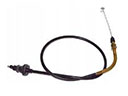 2001 Lincoln Town Car Accelerator Cable
 2001 Lincoln Town Car Air Duct
 2001 Lincoln Town Car Air Filter Box
 2001 Lincoln Town Car Fuel Filler Neck
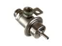 2001 Lincoln Town Car Fuel Pressure Regulator
 2001 Lincoln Town Car Fuel Pump Tank Seal
 2001 Lincoln Town Car Gas Cap
 2001 Lincoln Town Car Intake Manifold Gasket
 2001 Lincoln Town Car Throttle Body
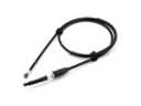 2001 Lincoln Town Car Throttle Cable