FordParts
My Garage
My Account
Cart
OEM Lincoln Town Car Intake Manifold
Engine Intake Manifold- Select Vehicle by Model
- Select Vehicle by VIN
Select Vehicle by Model
orMake
Model
Year
Select Vehicle by VIN
For the most accurate results, select vehicle by your VIN (Vehicle Identification Number).
3 Intake Manifolds found


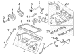
Lincoln Town Car Intake Manifold Part Number: 9W7Z-9424-A
$334.83 MSRP: $491.67You Save: $156.84 (32%)Lincoln Town Car Manifold Assembly - Inlet Part Number: PU7Z-9424-A
$334.83 MSRP: $491.67You Save: $156.84 (32%)
Lincoln Town Car Intake Manifold 0 Part Number: 6W7Z-9424-AA
Lincoln Town Car Intake Manifold
OEM Intake Manifold boasts unmatched quality. Each part goes through full quality checks. They adhere to Lincoln's official factory standards. These steps remove flaws and inconsistencies. So you can get Intake Manifold with long life and a perfect fit. Come to our website and find genuine Lincoln Town Car parts. We keep a wide inventory of OEM Town Car parts at the highly affordable prices. It's easy to search, compare, and pick what you need. You'll love the clear info and simple checkout. We offer top-rated customer service, and we reply fast. We also ship promptly to ensure your order arrives on time.
Another part that seems to be as vital in the intake process is the Intake Manifold as used in the Lincoln Town Car; this body part is mainly used to direct the fuel/air mixture to the cylinders in the engine for maximum efficiency and power output. Traditional manifolds tend to be fabricated from aluminum or cast iron but composite plastic material is used in the latest models because of the advantages of low weight and ability to dissipating heat. That way, air moves freely through the manifold's runners and strongly affects the matter of volumetric efficiency and the consequent combustion and performance. Variable-length intake manifolds (VLIM) or variable resonance induction systems (VRIS) are other issues that help vary the intake tract's length to enhance power, torque, and fuel efficiency by controlling the speed and pressure of the incoming air. These advancements, coupled with the application of new materials, are the aids towards creating better and stronger engines due to the control of the flow of air and fuel mixture. Intake manifold and gasket must be frequently checked and changed for leakage or damage to avoid affecting the efficiency of the engine.
Lincoln Town Car Intake Manifold Parts and Q&A
- Q: How to service the intake manifold on Lincoln Town Car?A:Service the intake manifold by first hoisting the vehicle on a lift at neutral position. Beginning the intake manifold service requires the removal of fuel tube spring lock coupling and battery ground cable together with draining engine cooling system fluid. Start by uninstalling the ACL with its outlet pipe and thorough removal of wiper mounting arm along with pivot shaft. The service starts by removing five retainer screws along with the two nuts from evaporative emission (EVAP) Canister Purge Valve bracket and the right-hand cowl extension. Disconnect the electrical wiring harness connector at the same time remove the 3 retention screws before taking out the LH cowl extension. Before removal disconnect the 8 fuel injector electrical connectors while removing all 8 ignition coil-on-plugs. Remove the shield bolts from the manifold intakes and detach the shield followed by disconnecting the brake booster vacuum hose attached to the manifold. The technician disconnects the EVAP canister purge valve hose quick connect couplings which are linked to the throttle body (TB) spacer and EVAP canister purge valve and the PCV tube quick connect coupling which connects to the TB spacer. Disconnect all electrical and vacuum tubes connecting the EGR system module and the intake manifold-to-TB spacer and the generator electric connector. Remove the 4 generator bracket bolts and separate the bracket after disconnection of generator wiring harness retainers from the generator bracket. First remove the coolant Thermostat followed by the throttle control and throttle position (TP) sensor electrical connector and then free the heater hose through its spring clamp. The installer should first remove the EGR system module tube then detach the wire harness retainer from the intake manifold crash bracket followed by removal of the intake manifold crash bracket bolt by securing the bracket away from the cylinder head with a rubber band or tie strap. The second crash bracket bolt needs to be removed on the intake manifold followed by the unclipping of vacuum connectors from the fuel rail pressure and temperature sensor then unfastening the rear wire harness retainer from the intake manifold. Dispose of the intake manifold gaskets after extracting the 8 bolts to finally proceed with cleaning the sealing surfaces. The installation requires proper alignment between the gasket locator tabs and cylinder head slots before adding new intake manifold gaskets. Engine replacement or repair due to upper engine failure requires a metal debris check of the intake manifold before installing a new one when metal contamination is detected. Use hand force to start the 8 intake manifold bolts before installing the 8 ignition coil-on-plugs. Fit the intake manifold crash bracket first before installing its bolts at (engine torque of 25 Nm [18 lb-ft]) while tightly tightening the intake manifold bolts at the specified order. The EGR system module tube then follows EGR system module tube installation with subsequent 10 Nm (89 lb-in) bolt installation on the intake manifold shield's two bolts. Tighten the throttle control and TP sensor electrical connectors before installing the coolant thermostat along with generator bracket screws at 10 Nm torque (89 lb-in). Plug in the generator electrical connector while fixing generator wiring harness retainers onto the generator bracket and uniting EVAP canister purge valve hose quick connect couplings with the TB and the EVAP canister purge valve. Attach the intake manifold vacuum hose to the TB spacer and join both the EGR system module vacuum and electrical connectors along with the PCV tube quick connect coupling to the TB spacer. Start by connecting the brake booster vacuum hose to the intake manifold and installing the heater hose with spring clamp and connecting the fuel rail pressure and temperature sensor vacuum and electrical connectors. First secure all 8 fuel injector electrical connectors before installing the wire harness retainer to the intake manifold rear side and connecting it to the crash bracket of the intake manifold. The LH cowl extension can be installed through three retainer screws with wiring harness electrical connector attachment before proceeding to attach the RH cowl extension with five retainer screws and tightening the 2 EVAP canister purge valve bracket nuts to 10 Nm torque (89 lb-in). The wiper mounting arm and pivot shaft installation process should be followed by connecting the fuel spring lock coupling then installing the ACL and outlet pipe before finally connecting the battery ground cable and filling and bleeding the engine cooling system.
- Q: How to remove the intake manifold on Lincoln Town Car?A:The removal process for the intake manifold begins with battery ground cable disconnect and complete engine cooling system drainage according to the following steps. Cut off power to the battery before disassembling the air cleaner resonator along with its outlet tube and the fuel line. You must start by taking off both wiper mounting arm and pivot shaft before moving on to dispose of the Drive Belt. The machinery procedures require lifting the vehicle with a hoist while disconnecting the electrical connector at the crankshaft position (CKP) sensor and the pin-type retainer from the A/C compressor bracket and the electrical connector from the A/C compressor. The first step includes removing the oil bypass filter followed by disconnecting the oil pressure sensor electrical connector together with the power steering pressure (PSP) switch electrical connector before detaching the harness position retainer. The maintenance requires separation of the RH Catalytic Converter assembly followed by EGR tube disconnection from the Exhaust Manifold position. Set the vehicle at its lowest position while disconnecting the electrical connector control of differential pressure feedback EGR. Remove all electrical wiring connectors that connect fuel charging to the eight Ignition Coils then to the eight Fuel Injectors. Disconnect the Accelerator Cable and speed control actuator cable together with the throttle return spring allowing their removal from the EGR tube heat shield before setting them aside. Proceed by taking out the bolts alongside the EGR tube heat shield followed by disconnecting evaporative emissions (EVAP) return tube and main chassis vacuum supply line and EGR Valve vacuum supply. The mechanic disconnects the positive crankcase ventilation (PCV) tube assembly at two points before removing it while also disconnecting the electrical connector from the EGR vacuum regulator solenoid and cutting the vacuum line from the EVAP Canister Purge Valve. Remove the generator mounting bracket after disconnecting the generator cable, electrical connector and harness location retainer. Detach the upper radiator hose while also disconnecting the electrical connectors from the idle air control (IAC) valve combined with the throttle position (TP) sensor and disconnect the heater water hose. Start by separating the wiring bracket from the EGR valve tube nut followed by removing the bracket after freeing the LH heated Oxygen Sensor and transmission electrical connectors from their positions. Remove the bracket by disconnecting wiring connectors then detaching the transmission harness from its stud followed by a nut then a bolt removal. Crews must first remove the throttle body bolts before they remove the throttle body. Later they should separate the fuel charging wiring pin-type retainer from the crash bracket to remove the cables from the crash bracket. Take off the crash bracket by using a bolt tool on its stud while also cutting the vacuum lines loose from each other then remove the vacuum harness. Separate the generator harness position retainer from the LH front stud while removing fuel charging wiring pin-type retainer from the rear of the manifold. The technician should unplug the ground wire connector from both the RH rear stud and the coolant temperature sensor connector. The fuel injection supply manifold with connective fuel injectors has to be separated from its studs before proceeding with ignition coils followed by water outlet adapter and water Thermostat before the removal of bolts and intake manifold. First remove the intake manifold gaskets before cleaning the surfaces where these gaskets will seal.


Related Lincoln Town Car Parts
 Lincoln Town Car Fuel Pump
 Lincoln Town Car Air Filter
 Lincoln Town Car Fuel Filter
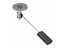 Lincoln Town Car Fuel Sending Unit
 Lincoln Town Car Fuel Tank
 Lincoln Town Car Air Duct
 Lincoln Town Car Air Filter Box
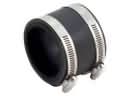 Lincoln Town Car Air Intake Coupling
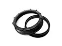 Lincoln Town Car Fuel Pump Seal
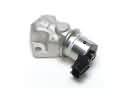 Lincoln Town Car Idle Control Valve
 Lincoln Town Car Intake Manifold Gasket
 Lincoln Town Car Throttle Body