FordParts
My Garage
My Account
Cart
OEM 2002 Ford Thunderbird Timing Cover
Engine Timing Cover- Select Vehicle by Model
- Select Vehicle by VIN
Select Vehicle by Model
orMake
Model
Year
Select Vehicle by VIN
For the most accurate results, select vehicle by your VIN (Vehicle Identification Number).
1 Timing Cover found

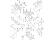
2002 Ford Thunderbird Timing Cover, Front Part Number: XW4Z-6019-CE
Product Specifications- Other Name: Cover - Cylinder Front; Engine Timing Cover; Front Cover
- Position: Front
- Base No.: 6019
- Item Weight: 8.50 Pounds
- Item Dimensions: 9.3 x 16.3 x 3.2 inches
- Condition: New
- Fitment Type: Direct Replacement
- SKU: XW4Z-6019-CE
- Warranty: This genuine part is guaranteed by Ford's factory warranty.
2002 Ford Thunderbird Timing Cover
If you're seeking quality and affordability, look no further than our extensive inventory of genuine 2002 Ford Thunderbird Timing Cover available at FordPartsDeal.com. You can confidently purchase our OEM 2002 Ford Thunderbird Timing Cover as they are supported by the manufacturer's warranty and our hassle-free return policy, alongside the benefit of our fast delivery service.
2002 Ford Thunderbird Timing Cover Parts Q&A
- Q: How to Service and Repair the Engine Front Timing Cover on 2002 Ford Thunderbird?A: Start the engine front cover repair by draining both engine oil and engine cooling system fluid. Start by taking off the LH and RH valve covers with their assembly and then need to loosen the water pump pulley bolts. Disassemble the procedure by taking out the generator along with its water pump pulley (keep the bolts) and bracket through nuts removal. Disconnect the lower radiator hose from the thermostat housing followed by disconnecting the heater hose and then remove both idler pulleys and crankshaft pulley and A/C compressor. The power steering reservoir requires draining after disconnecting both the power steering reservoir hose and the Power Steering Pressure (PSP) switch. The power steering pressure hose is covering one bolt which must be removed by loosening it in stages. After detaching power steering pump bolts you should set the pump aside before taking out the power steering pump bracket. After disconnecting and draining the hydraulic cooling fan pump reservoir you need to take off the electrical connector while also removing the hydraulic fan pump high-pressure hose bracket including one bolt which you should identify due to the hydraulic cooling fan pressure hose blockage. First remove the hydraulic cooling fan pump along with its bracket then allow the vehicle to lower before disconnecting five wiring harness clips to complete engine front cover removal by strictly following the bolt sequence. A plastic scraping tool should be used to clean sealing surfaces because it prevents scratches or gouges. Use new gaskets on the eight application locations before applying silicone gasket and sealant as you secure the front cover in four minutes or less to avoid oil leaks. Set the engine front cover onto the cylinder block before applying loose torque to the bolts. Then proceed to tighten them at 5 Nm (44 inch lbs.) followed by 10 Nm (89 inch lbs.). Follow these steps to install the hydraulic cooling fan pump bracket and its pump: First raise the vehicle, then gradually install the first bolt because of blocked passage and finish with both connections. Secure the hydraulic fan pump high-pressure hose bracket before connecting the electrical connector along with the hydraulic cooling fan reservoir hose. Install the power steering pump bracket followed by its installation of the power steering pump into position while attaching the Power Steering Pressure (PSP) switch and power steering reservoir hose. Reattach the A/C compressor followed by crankshaft pulley and idler pulleys then route the heater hose and lower radiator hose to the thermostat housing while inserting stud bolts and fastening them with nuts. The generator must receive new bolts that you should first place loosely on the water pump pulley before reinstalling the generator for two-stage bolt tightening beginning at 10 Nm (89 inch lbs.) then continuing to 45°. The last step involves putting back the engine cooling fan assembly together with the RH and LH valve covers and engine fill up with clean engine oil according to cooling system filling and bleeding procedures for hydraulic cooling fan and power steering system.
Related 2002 Ford Thunderbird Parts
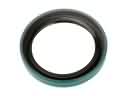 2002 Ford Thunderbird Crankshaft Seal
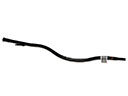 2002 Ford Thunderbird Dipstick Tube
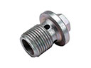 2002 Ford Thunderbird Drain Plug
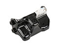 2002 Ford Thunderbird Engine Mount Bracket
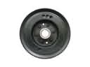 2002 Ford Thunderbird Harmonic Balancer
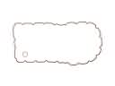 2002 Ford Thunderbird Oil Pan Gasket
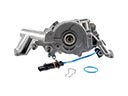 2002 Ford Thunderbird Oil Pump
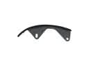 2002 Ford Thunderbird Timing Chain Guide
 2002 Ford Thunderbird Timing Chain Tensioner
 2002 Ford Thunderbird Timing Cover Gasket
 2002 Ford Thunderbird Valve Stem Seal
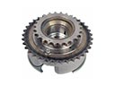 2002 Ford Thunderbird Variable Timing Sprocket