FordParts
My Garage
My Account
Cart
OEM 2003 Ford F-350 Super Duty Clutch Master Cylinder
- Select Vehicle by Model
- Select Vehicle by VIN
Select Vehicle by Model
orMake
Model
Year
Select Vehicle by VIN
For the most accurate results, select vehicle by your VIN (Vehicle Identification Number).
1 Clutch Master Cylinder found


2003 Ford F-350 Super Duty Master Cylinder Part Number: F81Z-7A543-FA
$63.47 MSRP: $97.50You Save: $34.03 (35%)Ships in 1-2 Business DaysProduct Specifications- Other Name: Master Cylinder Assembly; Clutch Master Cylinder; Brake Master Cylinder
- Base No.: 7A543
- Item Weight: 1.00 Pounds
- Item Dimensions: 9.2 x 8.2 x 3.0 inches
- Condition: New
- Fitment Type: Direct Replacement
- SKU: F81Z-7A543-FA
- Warranty: This genuine part is guaranteed by Ford's factory warranty.
2003 Ford F-350 Super Duty Clutch Master Cylinder
Achieve unprecedented performance experience with our genuine 2003 Ford F-350 Super Duty Clutch Master Cylinder. All our parts are engineered for a perfect fit and maximum durability to ensure that your F-350 Super Duty returns to factory condition. Specially designed for the 2003 Ford F-350 Super Duty, this Clutch Master Cylinder offers superior reliability and ease of installation for anyone.
If you're seeking quality and affordability, look no further than our extensive inventory of genuine 2003 Ford F-350 Super Duty Clutch Master Cylinder available at FordPartsDeal.com. You can confidently purchase our OEM 2003 Ford F-350 Super Duty Clutch Master Cylinder as they are supported by the manufacturer's warranty and our hassle-free return policy, alongside the benefit of our fast delivery service.
Related 2003 Ford F-350 Super Duty Parts
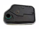 2003 Ford F-350 Super Duty Automatic Transmission Filter
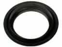 2003 Ford F-350 Super Duty Automatic Transmission Seal
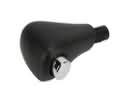 2003 Ford F-350 Super Duty Automatic Transmission Shift Levers
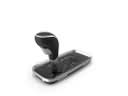 2003 Ford F-350 Super Duty Automatic Transmission Shifter
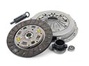 2003 Ford F-350 Super Duty Clutch Disc
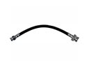 2003 Ford F-350 Super Duty Clutch Hose
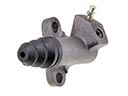 2003 Ford F-350 Super Duty Clutch Slave Cylinder
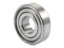 2003 Ford F-350 Super Duty Pilot Bearing
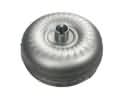 2003 Ford F-350 Super Duty Torque Converter
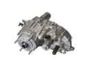 2003 Ford F-350 Super Duty Transfer Case
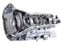 2003 Ford F-350 Super Duty Transmission Assembly
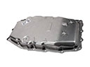 2003 Ford F-350 Super Duty Transmission Pan