FordParts
My Garage
My Account
Cart
OEM 2004 Mercury Sable Seat Switch
Seat Adjust Switch- Select Vehicle by Model
- Select Vehicle by VIN
Select Vehicle by Model
orMake
Model
Year
Select Vehicle by VIN
For the most accurate results, select vehicle by your VIN (Vehicle Identification Number).
1 Seat Switch found

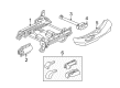
2004 Mercury Sable Control Switch, Front Part Number: 1L5Z-14A701-AA
Product Specifications- Other Name: Switch Assembly; Power Seat Switch, Front; Seat Switch; Switch; Power Seat Switch
- Manufacturer Note: BLACK
- Position: Front
- Base No.: 14A701
- Item Weight: 0.30 Pounds
- Item Dimensions: 7.6 x 3.9 x 3.8 inches
- Condition: New
- Fitment Type: Direct Replacement
- SKU: 1L5Z-14A701-AA
- Warranty: This genuine part is guaranteed by Ford's factory warranty.
2004 Mercury Sable Seat Switch
If you're seeking quality and affordability, look no further than our extensive inventory of genuine 2004 Mercury Sable Seat Switch available at FordPartsDeal.com. You can confidently purchase our OEM 2004 Mercury Sable Seat Switch as they are supported by the manufacturer's warranty and our hassle-free return policy, alongside the benefit of our fast delivery service.
2004 Mercury Sable Seat Switch Parts Q&A
- Q: How to Safely Service and Repair a Power Seat Switch on 2004 Mercury Sable?A: It is important to always use safety glasses when working on power seat switches on vehicles with air bags. Turn off the SRS prior to work. Check SRS functionality and then hand the car back. Disassemble the connector of the power seat track, take away shields and fit the switch. Then reassemble and re-power the SRS.
Related 2004 Mercury Sable Parts
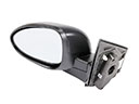 2004 Mercury Sable Car Mirror
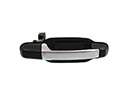 2004 Mercury Sable Door Handle
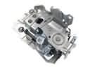 2004 Mercury Sable Door Latch Assembly
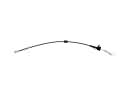 2004 Mercury Sable Door Latch Cable
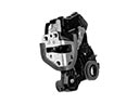 2004 Mercury Sable Door Lock
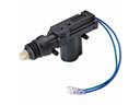 2004 Mercury Sable Door Lock Actuators
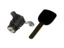 2004 Mercury Sable Door Lock Cylinder
 2004 Mercury Sable Floor Pan
 2004 Mercury Sable Mirror Cover
 2004 Mercury Sable Rear Passenger Door Handle Latch
 2004 Mercury Sable Seat Cover
 2004 Mercury Sable Weather Strip