FordParts
My Garage
My Account
Cart
OEM 2005 Ford Crown Victoria Seat Motor
Car Seat Motor- Select Vehicle by Model
- Select Vehicle by VIN
Select Vehicle by Model
orMake
Model
Year
Select Vehicle by VIN
For the most accurate results, select vehicle by your VIN (Vehicle Identification Number).
1 Seat Motor found

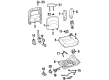
2005 Ford Crown Victoria Recline Motor Part Number: F3LY14547A
Product Specifications- Other Name: Motor Assembly - Seat Adjuster; Motor
- Item Weight: 4.10 Pounds
- Condition: New
- Fitment Type: Direct Replacement
- SKU: F3LY14547A
- Warranty: This genuine part is guaranteed by Ford's factory warranty.
2005 Ford Crown Victoria Seat Motor
If you're seeking quality and affordability, look no further than our extensive inventory of genuine 2005 Ford Crown Victoria Seat Motor available at FordPartsDeal.com. You can confidently purchase our OEM 2005 Ford Crown Victoria Seat Motor as they are supported by the manufacturer's warranty and our hassle-free return policy, alongside the benefit of our fast delivery service.
2005 Ford Crown Victoria Seat Motor Parts Q&A
- Q: How should one service the power seat motor safely and effectively on 2005 Ford Crown Victoria?A: During the maintenance of the power seat motor, wear a safety pair of glasses and discharge the SRS. Position the seat in the middle; otherwise, replace the seat track with a new one. Take off the fasteners, detach the motor and adjust the track. When reinstalling, make sure that it is properly aligned then install the seat and repower the SRS.
Related 2005 Ford Crown Victoria Parts
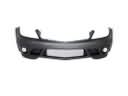 2005 Ford Crown Victoria Bumper
 2005 Ford Crown Victoria Emblem
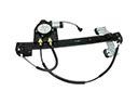 2005 Ford Crown Victoria Window Regulator
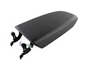 2005 Ford Crown Victoria Armrest
 2005 Ford Crown Victoria Cigarette Lighter
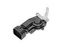 2005 Ford Crown Victoria Door Lock Actuator Motor
 2005 Ford Crown Victoria Front Door Striker
 2005 Ford Crown Victoria Liftgate Hinge
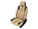 2005 Ford Crown Victoria Seat Cover
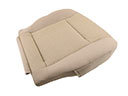 2005 Ford Crown Victoria Seat Cushion
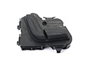 2005 Ford Crown Victoria Seat Switch
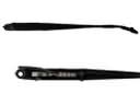 2005 Ford Crown Victoria Wiper Arm