FordParts
My Garage
My Account
Cart
OEM 2006 Ford Crown Victoria Intake Manifold
Engine Intake Manifold- Select Vehicle by Model
- Select Vehicle by VIN
Select Vehicle by Model
orMake
Model
Year
Select Vehicle by VIN
For the most accurate results, select vehicle by your VIN (Vehicle Identification Number).
1 Intake Manifold found


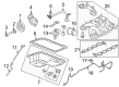
2006 Ford Crown Victoria Intake Manifold 0 Part Number: 6W7Z-9424-AA
Product Specifications- Other Name: Manifold Assembly - Inlet; Engine Intake Manifold
- Base No.: 9424
- Item Weight: 13.90 Pounds
- Item Dimensions: 20.4 x 16.6 x 9.4 inches
- Condition: New
- Fitment Type: Direct Replacement
- SKU: 6W7Z-9424-AA
- Warranty: This genuine part is guaranteed by Ford's factory warranty.
2006 Ford Crown Victoria Intake Manifold
If you're seeking quality and affordability, look no further than our extensive inventory of genuine 2006 Ford Crown Victoria Intake Manifold available at FordPartsDeal.com. You can confidently purchase our OEM 2006 Ford Crown Victoria Intake Manifold as they are supported by the manufacturer's warranty and our hassle-free return policy, alongside the benefit of our fast delivery service.
2006 Ford Crown Victoria Intake Manifold Parts Q&A
- Q: How to service the intake manifold on 2006 Ford Crown Victoria?A: The service of an intake manifold starts with disabling the fire suppression system if present followed by placing the vehicle on a hoist while keeping it in neutral. Service begins by disconnecting the spring lock coupling of the fuel tube along with the ground cable of the battery and the engine cooling system drainage. The servicing process begins by disconnecting the wiper mounting arm together with outlet pipe, air cleaner, pivot shaft. Separate the eight fuel injector electrical connectors from their sockets before taking out the eight ignition coil-on-plugs. Remove the two bolts securing the intake manifold shield and pull out the shield before detaching the vacuums connecting the brake booster to the quick connect evap canister purge valve coupling as well as the pcv tube from the throttle body spacer. The technician disconnects all vacuum hoses and electrical connections belonging to the intake manifold-to-tb spacer and the exhaust gas recirculation (egr) system module as well as the generator electrical connector. First disconnect the bolts from the four generator bracket while also taking off the bracket and removing the coolant thermostat. The first step includes disconnecting the throttle control and throttle position (tp) sensor electrical connector followed by spring clamp release on the heater hose and final disconnect of the hose itself. The egr system module tube should be removed first followed by wire harness retainer separation from the intake manifold crash bracket when present after which all bracket bolts must be taken out with proper cylinder head clearance. The technician should disconnect the fuel rail pressure and temperature sensor vacuum and electrical connectors while removing the wire harness retainers from the lh front fuel rail stud and the rear of the intake manifold and also disconnecting the ground connector from the rh rear fuel rail stud bolt. Removing the eight bolts securing the intake manifold allows for discarding its gaskets while you must clean all sealing surfaces. Attach the new intake manifold gaskets to their locator tabs before mounting the intake manifold while lightly tightening its eight bolts. Position the crash bracket of the intake manifold while reattaching the eight ignition coil-on-plugs before mounting the bolt and stud bolt loosely. Continued tightening of the eight bolts must begin with 25 Nm (18 ft. lbs.) following the sequence before fastening the crash bracket bolt to the same specification. The egr system module tube installation requires hand-tightening of two bolts to 12 Nm (9 ft. lbs.) after which the throttle control and tp sensor electrical connectors need to be connected. Connect the generator electrical connector after installing the coolant thermostat and generator bracket which must receive four bolts tightened to 10 Nm (89 inch lbs.). The evap canister purge valve hose should be wired from tb toward evap canister purge valve, along with the intake manifold vacuum hose attached to tb spacer and egr system module vacuum and electrical connectors. The port of the pcv tube should attach to the tb spacer then the brake booster intake manifold connection should follow. Afterward, secure the heater hose using a spring clamp. Rejoin the fuel rail pressure and temperature sensor vacuum and electrical connectors as well as the eight fuel injector electrical connectors and wire harness retainers. The ground connector must be attached to the rh rear fuel rail stud bolt after which you should reinstall the wiper mounting arm followed by connecting the fuel spring lock coupling to reattach the air cleaner and outlet pipe. Reconnect the battery ground wire and complete engine cooling system filling and bleeding procedures and reactivate the fire suppression system when it exists.
Related 2006 Ford Crown Victoria Parts
 2006 Ford Crown Victoria Fuel Pump
 2006 Ford Crown Victoria Air Filter
 2006 Ford Crown Victoria Air Filter Box
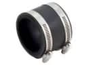 2006 Ford Crown Victoria Air Intake Coupling
 2006 Ford Crown Victoria Fuel Filter
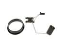 2006 Ford Crown Victoria Fuel Level Sensor
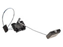 2006 Ford Crown Victoria Fuel Tank Sending Unit
 2006 Ford Crown Victoria Fuel Tank Strap
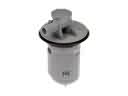 2006 Ford Crown Victoria Fuel Tank Vent Valve
 2006 Ford Crown Victoria Gas Cap
 2006 Ford Crown Victoria Intake Manifold Gasket
 2006 Ford Crown Victoria Mass Air Flow Sensor