FordParts
My Garage
My Account
Cart
OEM Mercury Villager Intake Manifold
Engine Intake Manifold- Select Vehicle by Model
- Select Vehicle by VIN
Select Vehicle by Model
orMake
Model
Year
Select Vehicle by VIN
For the most accurate results, select vehicle by your VIN (Vehicle Identification Number).
3 Intake Manifolds found

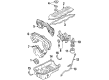
Mercury Villager Intake Manifold, Lower Part Number: XF5Z-9424-AA

Mercury Villager Intake Manifold Part Number: F3XY9424C
Mercury Villager Intake Manifold Part Number: 1F5Z9424AA
Mercury Villager Intake Manifold
OEM Intake Manifold boasts unmatched quality. Each part goes through full quality checks. They adhere to Mercury's official factory standards. These steps remove flaws and inconsistencies. So you can get Intake Manifold with long life and a perfect fit. Come to our website and find genuine Mercury Villager parts. We keep a wide inventory of OEM Villager parts at the highly affordable prices. It's easy to search, compare, and pick what you need. You'll love the clear info and simple checkout. We offer top-rated customer service, and we reply fast. We also ship promptly to ensure your order arrives on time.
The Mercury Villager Intake Manifold is one of the critical parts that tremendously improve the performance and sturdiness of the Mercury Villager minivan. Often noted for its effectiveness in terms of fuel consumption, the Intake Manifold is also important for the distribution of air or as a passage for the air fuel mixture to each cylinder head intake port as this influences the power output of the engine. Intended for numerous Villager models, the Intake Manifold is developed to enhance the air intake system so that the engine performs at its premier. The fact that the cast iron of the former designs has been replaced by composite plastics in the Mercuru Villager Intake Manifold not only enhances fuel efficiency but also cools the automobile engine making this product unique in the market. Some models go even further having such refinements as coolant passages and optional sensors that improve operation and protection of the engine. Another example of the Mercury Villager Intake Manifold is the variable-length intake manifolds (VLIM) that makes possible the adjustment of the length of the intake tract to improve performance depending on the driving environment. The Mercury Villager Intake Manifold is a very notorious part due to its reliability; this implies that it plays a very vital role of enhancing the general efficiency and safety of the vehicle in as much as it will contributing to the power of the automobile when on the road. Together with being the Intake Manifold in Mercury Villager range, it not only helps the engine perform but also prolong the life of the Villager and enhance the experience of lovers of the Mercury brand.
Mercury Villager Intake Manifold Parts and Q&A
- Q: How to service and repair the lower intake manifold on Mercury Villager?A:Before servicing or repairing the lower intake manifold it is necessary to reduce fuel system pressure. You must detach all i.e. disconnect electrical connectors from upper intake manifold and the Fuel Injector connectors and the Engine Coolant Temperature (ECT) sensor connector. Sanitize the H02S electrical connection by both removing ground wire bolts and unclipping socket retention on the bracket while removing the Heated Oxygen Sensor (H02S) electrical connector. Position the Positive Crankcase Ventilation (PCV) breather tube and wire harness to the side through disconnecting the PCV hose using the hose clamp followed by removing the wire straps. After disconnecting the water temperature sender electrical connection you should take out the bolt securing the spark plug wire bracket. It is necessary to exercise care near fuel components especially since these areas contain highly flammable mixtures and personnel must reduce fuel system pressure by unbolting connectors and releasing clamps and disconnecting fuel lines. The removal process includes taking out the fuel injection supply manifold bolts after both the manifold and insulators are detached from each other. The upper Radiator Hose requires release from its clamp and bolt so you can position it aside before removing the upper timing belt cover bolt. Proceed with disconnecting the coolant bypass hose from the water hose connection after releasing its clamp and perform the same operation with heater hose pipe and heater hose. The two-step method helps to separate lower intake manifold bolts and nuts in their specified sequence before removing the lower intake manifold while discarding the gaskets. The installation process requires fitting new lower intake manifold gaskets and lower intake manifold to the vehicle before installing nuts and bolts according to their specified sequence and performing a 3-step tightening process which starts at 4 Nm (35 inch lbs.) followed by 9 Nm (80 inch lbs.) twice. Begin with securing the heater hose pipe to the heater hose after you place the clamp onto it. Move to connect the coolant bypass hose to the water hose connection then secure its clamp. Before mounting the upper timing belt cover bolt install the upper radiator hose while also ensuring the fuel injection supply manifold insulators are in position before bolt installation. The fuel lines require positioning for installation of bolts before a fuel hose connection with clamping. The next steps include fastening the spark plug wire bracket bolt and hooking up the water temperature indicator sender electrical connector before positioning the PCV breather tube with its wire harness. Users then connect the PCV breather hose with new wire straps installed. The installation process requires connecting the H02S electrical connector then clipping the wire harness onto the bracket before bolt installation of the ground wire. When finishing the installation connect both electrical connectors which serve the fuel injectors and ECT sensor before adding the upper intake manifold.

Related Mercury Villager Parts
 Mercury Villager Air Duct
 Mercury Villager Air Filter
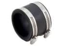 Mercury Villager Air Intake Coupling
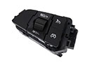 Mercury Villager Cruise Control Switch
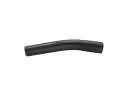 Mercury Villager Fuel Filler Hose
 Mercury Villager Fuel Filler Neck
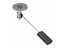 Mercury Villager Fuel Sending Unit
 Mercury Villager Gas Cap
 Mercury Villager Intake Manifold Gasket
 Mercury Villager Throttle Body
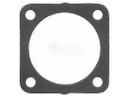 Mercury Villager Throttle Body Gasket
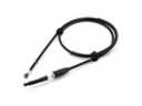 Mercury Villager Throttle Cable