
Popular OEM Mercury Villager Parts
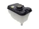
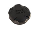
- Body & Hardware Parts View More >
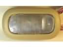
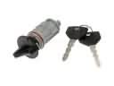
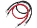
- Electrical Parts View More >
- Interior & Exterior Trim Parts View More >
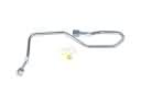
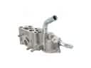
- Air & Fuel Delivery Parts View More >
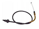
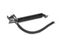
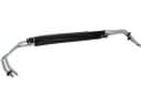
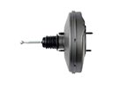
- Steering Parts View More >
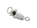
- Emission Control & Exhaust Parts View More >
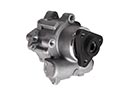
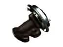
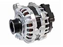
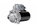
- Charging & Starting Parts View More >
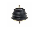
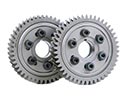
- Engine Parts View More >
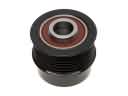
- Belts & Cooling Parts View More >
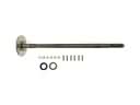
- Suspension Parts View More >
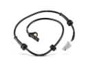
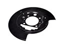
- Brakes Parts View More >
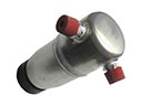
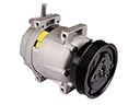
- A/C & Heating Parts View More >


Why Buy Genuine Mercury Villager Parts From FordPartsDeal.com
FordPartsDeal.com offers a smart and convenient way to buy genuine parts online. We sell new OEM Mercury Villager parts, including Headlights & Lighting. Authorized dealers directly provide all the Mercury Villager parts and assemblies to ensure the optimal quality and fit. We also provide all properly fitting Mercury Villager parts, such as Transmission specific to your model. When you shop here, you get real Mercury value at highly competitive prices. All our products come with the same Mercury warranty available at other dealerships. Our easy-to-use catalog helps you quickly identify the right part for your car. You'll receive fast shipping from our warehouse network, keeping your Mercury Villager running smoothly. Our staff consists of Mercury professionals who are ready to assist you. We aim to treat each customer as if they were stepping out of a Mercury showroom. VIN verification and our live support ensure that the part you order is the right Mercury Villager part for your vehicle.
The Mercury Villager was launched as a result of the Ford-Nissan partnership, sharing its platform with the Quest but featuring unique styling and design. Mercury unveiled the Villager minivan at the Chicago Auto Show in 1992 for a 1993 production year and manufacturing took place in both Canadian and American facilities throughout its two-generation lifecycle. During the first generation the Mercury Villager integrated a VG30E V6 engine with a non-interference design and a 3.0L V6 to deliver 151 horsepower through four-speed automatic transmission output. The second-generation Mercury Villager, introduced in 1999, was powered by a 3.0L V6 engine producing 170 horsepower and 190 lb-ft of torque, paired with a four-speed automatic transmission. Front-side airbags and anti-lock brakes were included as standard in later generations of the Mercury Villager, with various trim options available, including GS, LS, and the Nautica Special Edition. Market-ready exterior modifications added integrated fog lights together with satin-finish grille updates to complement interior changes bringing better instrumentation and better Autovision entertainment capabilities to the vehicle. Reliability together with performance enhancement requires Mercury Villager owners to use original parts specifically designed for the Villager according to its original quality benchmarks.
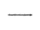
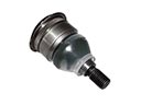
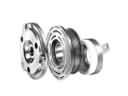
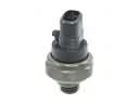
Mercury Villager issues group into fuel delivery, ignition timing, and front suspension safety. In fuel delivery, a failing fuel injector causes rough idle, misfire, and weak acceleration. The Villager may start cold, then stumble under load without a warning lamp. Check injector pulse, ohm balance, and rail pressure, then replace clogged units as required. Inspect connectors for corrosion that blocks power, and verify harness grounds along the rail. Ignition concerns center on the distributor, where a seized shaft bearing causes stalls or no start. The Villager may crank normally, then die at lights or refuse to restart hot. Confirm distributor play, check cam and crank signals, and install a quality replacement assembly. In the front suspension, moisture can damage lower ball joints and increase steering wander. The Villager may clunk over bumps and pull during braking on uneven roads. Replace lower ball joints per recall guidance, then align the Villager and recheck tire wear. Finish with a verification drive so the Mercury Villager idles smoothly and tracks straight. Record codes, fuel trims, and charging voltage using Mercury service procedures for reference. Schedule periodic inspections so the Mercury Villager remains reliable in varied duty cycles.
Mercury Villager Parts and Q&A
- Q: How to service and repair the lower intake manifold on Mercury Villager?A:Removing the upper intake manifold and relieving the pressure in the fuel system To service and repair the lower intake manifold. Disassemble different electrical connectors and hoses and take away lower intake manifold and gaskets. To install, fit the gaskets and the manifold, and then reassemble everything in order.
- Q: How to service and repair the steering wheel on Mercury Villager?A:In order to service and repair the steering wheel, begin by dismantling the driver side air bag module, using Restraint Systems service precautions. Then, unscrew the electrical connector and remove the steering wheel nut. With the right tool, remove the steering wheel. Installation To install, reverse the steps of removal.
- Q: How to service and repair the throttle body on Mercury Villager?A:In order to service throttle body, disconnect battery, drain cooling system and take off air cleaner tube. Disassemble electric connector, cables, and coolant hoses. Disassemble throttle body and place a new gasket and fix it. Reattach all and refill the cooling system and reattach the battery.


