FordParts
My Garage
My Account
Cart
OEM 2000 Ford Mustang Intake Manifold
Engine Intake Manifold- Select Vehicle by Model
- Select Vehicle by VIN
Select Vehicle by Model
orMake
Model
Year
Select Vehicle by VIN
For the most accurate results, select vehicle by your VIN (Vehicle Identification Number).
3 Intake Manifolds found
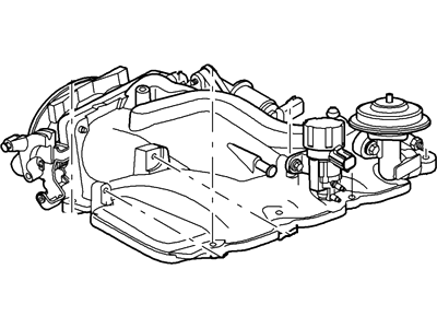
2000 Ford Mustang Intake Manifold, Upper Part Number: 3R3Z-9424-DA
Product Specifications- Other Name: Manifold Assembly - Inlet
- Manufacturer Note: Complete Assembly
- Position: Upper
- Base No.: 9424A
- Item Weight: 8.70 Pounds
- Item Dimensions: 16.0 x 16.9 x 14.3 inches
- Condition: New
- Fitment Type: Direct Replacement
- SKU: 3R3Z-9424-DA
- Warranty: This genuine part is guaranteed by Ford's factory warranty.
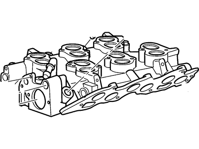
2000 Ford Mustang Intake Manifold, Lower Part Number: YR3Z-9424-AA
Product Specifications- Other Name: Manifold Assembly - Inlet
- Position: Lower
- Base No.: 9424
- Item Weight: 18.50 Pounds
- Item Dimensions: 16.3 x 17.1 x 14.2 inches
- Condition: New
- Fitment Type: Direct Replacement
- SKU: YR3Z-9424-AA
- Warranty: This genuine part is guaranteed by Ford's factory warranty.
2000 Ford Mustang Intake Manifold, Upper Part Number: XR3Z-9424-BF
Product Specifications- Other Name: Manifold Assembly - Inlet
- Position: Upper
- Base No.: 9424
- Item Weight: 15.40 Pounds
- Item Dimensions: 16.4 x 17.1 x 14.0 inches
- Condition: New
- Fitment Type: Direct Replacement
- SKU: XR3Z-9424-BF
- Warranty: This genuine part is guaranteed by Ford's factory warranty.
2000 Ford Mustang Intake Manifold
If you're seeking quality and affordability, look no further than our extensive inventory of genuine 2000 Ford Mustang Intake Manifold available at FordPartsDeal.com. You can confidently purchase our OEM 2000 Ford Mustang Intake Manifold as they are supported by the manufacturer's warranty and our hassle-free return policy, alongside the benefit of our fast delivery service.
2000 Ford Mustang Intake Manifold Parts Q&A
- Q: How to service and repair the lower intake manifold on 2000 Ford Mustang?A: A technician should start service and repair work on the lower intake manifold by eliminating the upper intake manifold followed by partial cooling system drainage. First drain the fuel system pressure before disconnecting both the fuel pressure sensor electric connector and the fuel supply manifold. The technician should place the engine wire harness to the side and then disconnect the heater hose followed by setting the spark plug wire loom to the side. The service requires the Disconnection of Exhaust Gas Recirculation (EGR) vacuum tube by removing the stud bolt. The exhaust air supply valve assembly needs removal when equipped by first loosening the tube nut before disconnecting the air tube and vacuum tube which requires nut removal. The upper radiator hose and water bypass hose together with the EGR tube require removal followed by detaching two electrical connectors. Separate the bypass tube bolt and extract the fuel injection supply manifold together with fuel injectors as one unit while remembering short and long bolt positions for future reinstallment. You should access the lower intake manifold by removing eight short bolts and six long bolts before eliminating the gaskets from the intake manifold assembly. Install lower intake manifold front and rear end seals and intake manifold gaskets by applying Silicone Gasket and Sealant F7AZ-19554-EA which meets Ford specification WSE-M4G323-A4 on the mounting points. You need to install the lower intake manifold within four minutes after putting on the sealant. Delay installing the lower intake manifold only after applying sealant to its mounting points then bolt it down accordance with this sequence: 5 Nm (44 inch lbs.) followed by 10 Nm (89 inch lbs.). The installation process starts with combined installation of the fuel injection supply manifold and bolts then adds the bypass tube bolt before reconnecting all electrical connectors. The operation requires reattaching coolant hoses together with attaching the EGR tube and EGR vacuum tube while installing the exhaust air supply valve by tightening the nut and joining air and vacuum tubes. Install the stud bolt first and then position both the spark plug wire loom and heater hose before connecting the pin-type retainers to the engine wire harness. Finish the installation by joining the fuel injection supply manifold with the fuel pressure electrical connector while adding the upper intake manifold but always do cooling system bleeding correctly to secure proper engine cooling parameters.


