FordParts
My Garage
My Account
Cart
OEM 2000 Lincoln Continental Intake Manifold
Engine Intake Manifold- Select Vehicle by Model
- Select Vehicle by VIN
Select Vehicle by Model
orMake
Model
Year
Select Vehicle by VIN
For the most accurate results, select vehicle by your VIN (Vehicle Identification Number).
1 Intake Manifold found


2000 Lincoln Continental Manifold Part Number: YF3Z-9424-AA
Product Specifications- Other Name: Manifold Assembly - Inlet; Intake Manifold
- Base No.: 9424
- Item Weight: 29.40 Pounds
- Item Dimensions: 17.8 x 16.3 x 13.3 inches
- Condition: New
- Fitment Type: Direct Replacement
- SKU: YF3Z-9424-AA
- Warranty: This genuine part is guaranteed by Ford's factory warranty.
2000 Lincoln Continental Intake Manifold
If you're seeking quality and affordability, look no further than our extensive inventory of genuine 2000 Lincoln Continental Intake Manifold available at FordPartsDeal.com. You can confidently purchase our OEM 2000 Lincoln Continental Intake Manifold as they are supported by the manufacturer's warranty and our hassle-free return policy, alongside the benefit of our fast delivery service.
2000 Lincoln Continental Intake Manifold Parts Q&A
- Q: How to service and repair the intake manifold on 2000 Lincoln Continental?A: The repair process for intake manifold service starts by removing engine cooling system fluids then disconnecting the ground cable from the battery. First disconnect the fuel line while separating the air cleaner outlet tube. Start by disconnecting the engine sensor control wiring that uses two nuts to mount on valve covers. Position the generator battery lead by removing its nut and bolt. Follow with a disconnection of the generator electrical connector and complete the process by removing the generator mounting bracket through bolt and nut removal. Detach the coolant hoses from the water bypass tube while removing its attached nuts before you pull out the bypass tube. Disengage the mass air flow sensor connector from the accelerator snow shield after detaching it along with its disconnect. Then uninstall the shield with its bolt and pushpin. First disconnect the accelerator cable and speed control actuator cable from the throttle body followed by bolt removal of the accelerator bracket to position the components aside. Remove all connections from the EGR valve including the chassis vacuum supply tube, positive crankcase ventilation tube, engine vacuum supply line and fuel pressure sensor vacuum line along with the electrical connector and evaporative emissions return line, heater water hose, and vacuum lines from the EGR vacuum regulator solenoid and EGR valve. The technicians disconnect the electrical connectors which service eight fuel injectors and two sensors of the engine control valve and mass airflow and idle air control valve. Start the EGR tube removal by disconnecting it at both the EGR valve and the four LH ignition coils then continue with the starter electrical connectors and place the fuel charging wiring to the side. Remove the bolts and studs from the intake manifold assembly following a three-step sequence in order to extract the assembly before discarding and replacing the gaskets. The next step includes removing EGR valve and idle air control valve by using respective bolt removers and taking out the throttle body while performing a gasket replacement when necessary. The installer needs to clean all areas where gaskets will seal before applying new intake manifold gaskets. The procedure involves attaching the throttle body to its gasket and bolt installation to 9 Nm (80 inch lbs.) torque followed by an extra 90 degrees of manual torque. The installation process must start with a new idle air control gasket and the valve bolt should be tightened to 9 Nm (80 inch lbs.) with another 90-degree turn, followed by the EGR valve gasket and bolt installation with first-stage torque to 20 Nm (14 ft. lbs.) before final 90-degree turn. Install the intake manifold assembly while setting the fuel injectors right and adding the bolts first in a loose manner then tighten the bolts and studs using the designated sequence. Position the wiring holders through studs before connecting the vacuum line and EGR tube to the EGR valve then link the engine control sensors to the valve and throttle position sensor along with eight fuel injectors. Install all engine control sensor wiring covers before connecting each electrical component to the EGR vacuum regulator and fitting the heater water hose, main emission hose and both vacuum lines and electrical connector to the fuel injection pressure sensor. Install the accelerator cable bracket before connecting the accelerator cable and speed control actuator cable to it while reattaching the chassis vacuum supply tube and positive crankcase ventilation tube along with the engine vacuum supply line. Position the snow shield while installing its bolt with pushpin before connecting the mass air flow sensor to the shield and replacing the necessary O-ring seals by avoiding any cutting damage. The cylinder head O-ring sealing surfaces need cleaning before Premium Engine Coolant E2FZ-19549-AA or equivalent coat is applied to the water bypass tube sealing O-rings. Place the water bypass tube support braces on the intake manifold inner studs then fasten the water bypass tube with two nuts. First reposition the generator mounting bracket before you connect the generator electrical connector and position the generator battery lead then install the nut and bolt. The first step is to attach the engine control sensor wiring electrical connector to the engine coolant temperature sensor followed by hose reinstallation on the bypass tube. Then bolt the two nuts retaining the engine control sensor wiring at the valve cover. As the final step connect the fuel line, air cleaner outlet tube, battery ground cable alongside starter and ignition coils before performing a cooling system fill and bleed.
Related 2000 Lincoln Continental Parts
 2000 Lincoln Continental Air Duct
 2000 Lincoln Continental Air Filter
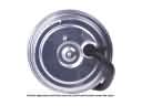 2000 Lincoln Continental Cruise Control Servo
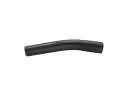 2000 Lincoln Continental Fuel Filler Hose
 2000 Lincoln Continental Fuel Filter
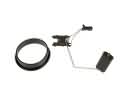 2000 Lincoln Continental Fuel Level Sensor
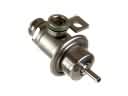 2000 Lincoln Continental Fuel Pressure Regulator
 2000 Lincoln Continental Fuel Pump Seal
 2000 Lincoln Continental Fuel Pump Tank Seal
 2000 Lincoln Continental Fuel Tank Lock Ring
 2000 Lincoln Continental Gas Cap
 2000 Lincoln Continental Intake Manifold Gasket