FordParts
My Garage
My Account
Cart
OEM 2001 Ford Explorer Sport Turn Signal Switch
Turn Signal Indicator Switch- Select Vehicle by Model
- Select Vehicle by VIN
Select Vehicle by Model
orMake
Model
Year
Select Vehicle by VIN
For the most accurate results, select vehicle by your VIN (Vehicle Identification Number).
1 Turn Signal Switch found


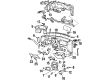
2001 Ford Explorer Sport Turn Signal Switch Part Number: YL5Z-13K359-AAA
$84.09 MSRP: $138.36You Save: $54.27 (40%)Product Specifications- Other Name: Switch Assembly - Direction Indicator; Turn Signal & Combination Lever; Hazard Flasher; Multi-Function Switch.; Turn Signal & Hazard Switch
- Base No.: 13K359
- Item Weight: 0.90 Pounds
- Item Dimensions: 6.2 x 4.5 x 10.4 inches
- Condition: New
- Fitment Type: Direct Replacement
- SKU: YL5Z-13K359-AAA
- Warranty: This genuine part is guaranteed by Ford's factory warranty.
2001 Ford Explorer Sport Turn Signal Switch
Achieve unprecedented performance experience with our genuine 2001 Ford Explorer Sport Turn Signal Switch. All our parts are engineered for a perfect fit and maximum durability to ensure that your Explorer Sport returns to factory condition. Specially designed for the 2001 Ford Explorer Sport, this Turn Signal Switch offers superior reliability and ease of installation for anyone.
If you're seeking quality and affordability, look no further than our extensive inventory of genuine 2001 Ford Explorer Sport Turn Signal Switch available at FordPartsDeal.com. You can confidently purchase our OEM 2001 Ford Explorer Sport Turn Signal Switch as they are supported by the manufacturer's warranty and our hassle-free return policy, alongside the benefit of our fast delivery service.
Related 2001 Ford Explorer Sport Parts
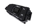 2001 Ford Explorer Sport Cruise Control Switch
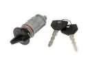 2001 Ford Explorer Sport Ignition Lock Cylinder
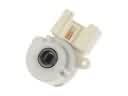 2001 Ford Explorer Sport Ignition Switch
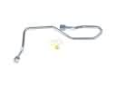 2001 Ford Explorer Sport Power Steering Hose
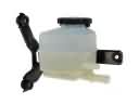 2001 Ford Explorer Sport Power Steering Reservoir
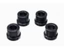 2001 Ford Explorer Sport Rack & Pinion Bushing
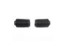 2001 Ford Explorer Sport Rack And Pinion
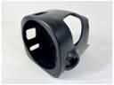 2001 Ford Explorer Sport Steering Column Cover
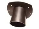 2001 Ford Explorer Sport Steering Column Seal
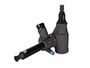 2001 Ford Explorer Sport Steering Gear Box
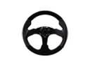 2001 Ford Explorer Sport Steering Wheel
 2001 Ford Explorer Sport Tie Rod End