FordParts
My Garage
My Account
Cart
OEM 2001 Ford Taurus Clock Spring
Spiral Cable Clock Spring- Select Vehicle by Model
- Select Vehicle by VIN
Select Vehicle by Model
orMake
Model
Year
Select Vehicle by VIN
For the most accurate results, select vehicle by your VIN (Vehicle Identification Number).
1 Clock Spring found

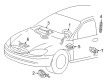
2001 Ford Taurus Clockspring Part Number: YF1Z-14A664-AA
Product Specifications- Other Name: Cover And Contact Plate; Air Bag Clockspring; Cover And Contact Plate Assembly
- Manufacturer Note: Snap on type, Atlanta and Chicago built
- Base No.: 14A664
- Item Weight: 0.80 Pounds
- Item Dimensions: 8.4 x 6.2 x 3.1 inches
- Condition: New
- Fitment Type: Direct Replacement
- SKU: YF1Z-14A664-AA
- Warranty: This genuine part is guaranteed by Ford's factory warranty.
2001 Ford Taurus Clock Spring
If you're seeking quality and affordability, look no further than our extensive inventory of genuine 2001 Ford Taurus Clock Spring available at FordPartsDeal.com. You can confidently purchase our OEM 2001 Ford Taurus Clock Spring as they are supported by the manufacturer's warranty and our hassle-free return policy, alongside the benefit of our fast delivery service.
2001 Ford Taurus Clock Spring Parts Q&A
- Q: What Precautions Should Be Taken When Servicing the Clock Spring Assembly on 2001 Ford Taurus?A: Wear safety glasses and employ care when handling air bag modules when servicing the Clock Spring assembly. Make sure that the SRS is running and then handover the vehicle. Have the right procedures during removal and installation, such as centering Clock Spring and fixing of all parts. And lastly, repower and install the steering wheel.
Related 2001 Ford Taurus Parts
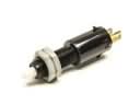 2001 Ford Taurus Brake Light Switch
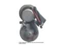 2001 Ford Taurus ABS Pump And Motor Assembly
 2001 Ford Taurus Air Bag
 2001 Ford Taurus Air Bag Control Module
 2001 Ford Taurus Air Bag Sensor
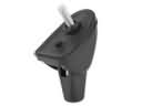 2001 Ford Taurus Antenna Base
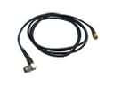 2001 Ford Taurus Antenna Cable
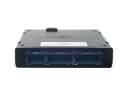 2001 Ford Taurus Body Control Module
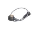 2001 Ford Taurus Knock Sensor
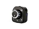 2001 Ford Taurus Mirror Switch
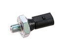 2001 Ford Taurus Oil Pressure Switch
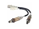 2001 Ford Taurus Oxygen Sensors