FordParts
My Garage
My Account
Cart
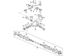
OEM 2001 Lincoln LS Drive Shaft
Axle Shaft- Select Vehicle by Model
- Select Vehicle by VIN
Select Vehicle by Model
orMake
Model
Year
Select Vehicle by VIN
For the most accurate results, select vehicle by your VIN (Vehicle Identification Number).
2 Drive Shafts found

2001 Lincoln LS Drive Shaft Part Number: 3W4Z-4R602-AB
Product Specifications- Other Name: Shaft Assembly - Drive; Driveshaft; Drive Shaft Assembly
- Base No.: 4R602
- Item Weight: 20.00 Pounds
- Item Dimensions: 26.2 x 6.1 x 15.0 inches
- Condition: New
- Fitment Type: Direct Replacement
- SKU: 3W4Z-4R602-AB
- Warranty: This genuine part is guaranteed by Ford's factory warranty.
2001 Lincoln LS Drive Shaft Part Number: 3W4Z-4R602-BB
Product Specifications- Other Name: Shaft Assembly - Drive; Driveshaft; Drive Shaft Assembly
- Base No.: 4R602
- Item Dimensions: 25.2 x 6.1 x 15.6 inches
- Condition: New
- Fitment Type: Direct Replacement
- SKU: 3W4Z-4R602-BB
- Warranty: This genuine part is guaranteed by Ford's factory warranty.
2001 Lincoln LS Drive Shaft
If you're seeking quality and affordability, look no further than our extensive inventory of genuine 2001 Lincoln LS Drive Shaft available at FordPartsDeal.com. You can confidently purchase our OEM 2001 Lincoln LS Drive Shaft as they are supported by the manufacturer's warranty and our hassle-free return policy, alongside the benefit of our fast delivery service.
2001 Lincoln LS Drive Shaft Parts Q&A
- Q: How to Service and Repair the Drive Shaft on 2001 Lincoln LS?A: Starting the drive/propeller shaft repair requires lifting the vehicle and using body brace removal and heat shield bolt removal as the first steps. Protect the driveshaft by securely placing the heat shield outside normal striking distance of the shaft during the balancing process. Latch the heat shield forward by using a wire as a securing method. The following operation should start with wheel and tire assembly removal from the rear position and wheel nut installation to keep them from unfastening while you perform the balancing steps. After lowering the vehicle you should activate the hood to boost temperature reduction while also disabling vehicles with traction control features when available. Use an assistant who should assume driving position before raising the vehicle. Keep speeds below 70 mph since the assistant accelerates to achieve the speed needed for observing tire unbalanced conditions. Rotational parts and hot exhaust components require clearance around the body along with hands, hair, head and clothing. A qualified marker needs placement inside a 305 mm (12 inch) long plastic pipe while using the heat shield lip as support to reach the driveshaft until the scribe touches its surface. Check the driveshaft mark after engine shutdown by the assistant; a mark that is not fully visible indicates the causes unbalance. When an imbalance exists you should install a 2.75-gram weighted nut onto the flex coupling bolt that faces the opposite side of the mark. This bolt represents the light side of the driveshaft. Continue with the marking process and reinstall every component after the new mark reaches 360-degrees during testing. The measurement process should begin again by using a 5.6-gram weighted nut instead of the 2.75-gram version when vibration continues. Continue the marking process after finding that the new mark is not 360-degrees by moving the weighted nut to adjacent bolts. The installation of a new driveshaft assembly should become the final step when the condition fails to improve after marking and using weighted nuts. The installation of all parts should follow the best achievable outcome before conducting a road test of the vehicle.
Related 2001 Lincoln LS Parts
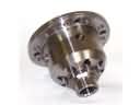 2001 Lincoln LS Differential
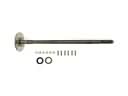 2001 Lincoln LS Axle Shaft
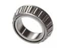 2001 Lincoln LS Differential Bearing
 2001 Lincoln LS Differential Pinion Bearing
 2001 Lincoln LS Differential Seal
 2001 Lincoln LS Driveshaft Yokes
 2001 Lincoln LS Pinion Bearing
 2001 Lincoln LS Pinion Washer
 2001 Lincoln LS Slip Yoke