FordParts
My Garage
My Account
Cart
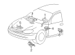
OEM 2002 Mercury Sable Clock Spring
Spiral Cable Clock Spring- Select Vehicle by Model
- Select Vehicle by VIN
Select Vehicle by Model
orMake
Model
Year
Select Vehicle by VIN
For the most accurate results, select vehicle by your VIN (Vehicle Identification Number).
1 Clock Spring found

2002 Mercury Sable Clockspring Part Number: 2F1Z-14A664-AA
Product Specifications- Other Name: Cover And Contact Plate Assembly; Air Bag Clockspring
- Manufacturer Note: Snap on type, Atlanta and Chicago built
- Base No.: 14A664
- Item Weight: 0.30 Pounds
- Item Dimensions: 6.4 x 6.2 x 2.9 inches
- Condition: New
- Fitment Type: Direct Replacement
- SKU: 2F1Z-14A664-AA
- Warranty: This genuine part is guaranteed by Ford's factory warranty.
2002 Mercury Sable Clock Spring
If you're seeking quality and affordability, look no further than our extensive inventory of genuine 2002 Mercury Sable Clock Spring available at FordPartsDeal.com. You can confidently purchase our OEM 2002 Mercury Sable Clock Spring as they are supported by the manufacturer's warranty and our hassle-free return policy, alongside the benefit of our fast delivery service.
2002 Mercury Sable Clock Spring Parts Q&A
- Q: What Precautions Should Be Taken When Servicing the Clock Spring on 2002 Mercury Sable?A: It is essential to wear safety glasses during air bag sliding contact service to protect from potential injuries that might occur due to accidental air bag deployment. You must carry a live air bag module with its air bag and trim cover aimed toward the floor while keeping them directed away from your body and never place it with the trim cover touching the ground. Avoid using memory saver devices. The RCM fuse removal and ignition switch activation causes the air bag warning lamp to turn on because this operation does not indicate an SRS fault. A vehicle must be prepared for release to market when the SRS demonstrates full functionality without any detected faults. A new part needs installation for repairs before checking the diagnostics once again after putting back the original part. The system power must be turned off before checking the wheel position. To begin uninstall the steering wheel (3600) and proceed to the lower steering column opening cover with reinforcement by removing bolts followed by releasing retaining clips. You will need to use two small pieces of masking tape on the Clock Spring before lowering the steering column to its maximum position and taking off the handle and shank assembly of the wheel tilt mechanism. Push on the cylinder release tab which is in the RUN position until the tab upward while you pull the apparatus outward. The installation process begins by removing steering column shrouds at both lower and upper bands while extracting the PATS transmitter after its retaining screw removal and also disconnecting the key-in-ignition warning indicator switch. The shift indicator tube needs to be detached during column shift operations after removing both the cable and screw. Unplug the Clock Spring electrical connector pin-type retainers before redirecting the Clock Spring wire harness to run along the steering column through its holders. Start by using a small tool to open the Clock Spring retaining clips which enables the Clock Spring removal. During installation process users should remove the key from the ignition yet keep the rotor fixed at its central point while it stays stationary. To recenter the rotor you should fix the outer housing and push and release the anti-rotation tab before turning the rotor counterclockwise until resistance develops and then turning it clockwise three complete turns to the center point. The removal of tape on reuse requires avoiding any turning motion of the Clock Spring components. Interfitting the Clock Spring with the steering column while securing retaining clips before connecting the wire harness. The shift indicator tube must be installed followed by a shift indicator cable attachment when dealing with vehicles featuring column shifts. The installation of upper and lower steering column shrouds should precede connecting electric Clock Spring wires along with adding the key-in-ignition warning indicator switch and positioning the PATS transmitter. Fasten the ignition switch lock cylinder to the steering column assembly by attaching the tilt wheel handle and shank together with the lower steering column opening cover made of reinforcement at 7 Nm (62 lb in). Finish the installation of the steering wheel after powering the system.
Related 2002 Mercury Sable Parts
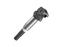 2002 Mercury Sable Ignition Coil
 2002 Mercury Sable Air Bag
 2002 Mercury Sable Air Bag Control Module
 2002 Mercury Sable Air Bag Sensor
 2002 Mercury Sable Antenna Base
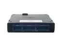 2002 Mercury Sable Body Control Module
 2002 Mercury Sable Brake Light Switch
 2002 Mercury Sable Knock Sensor
 2002 Mercury Sable Seat Belt
 2002 Mercury Sable Spark Plug Wire
 2002 Mercury Sable Tachometer
 2002 Mercury Sable Window Switch