FordParts
My Garage
My Account
Cart
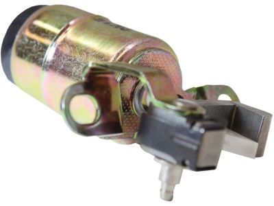
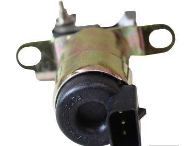
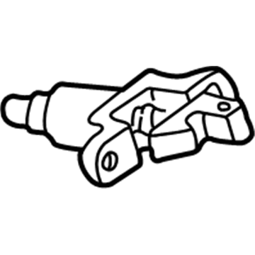
OEM 2003 Ford Taurus Shift Interlock Solenoid
Shift Lock Actuator- Select Vehicle by Model
- Select Vehicle by VIN
Select Vehicle by Model
orMake
Model
Year
Select Vehicle by VIN
For the most accurate results, select vehicle by your VIN (Vehicle Identification Number).
1 Shift Interlock Solenoid found

2003 Ford Taurus Lock Actuator Part Number: F2DZ-3Z719-A
$56.22 MSRP: $81.83You Save: $25.61 (32%)Product Specifications- Other Name: Solenoid Assembly; Shift Interlock Solenoid; Interlock Solenoid; Solenoid; Actuator
- Replaces: YC3Z-3Z719-AA
- Base No.: 3Z719
- Item Weight: 0.40 Pounds
- Condition: New
- Fitment Type: Direct Replacement
- SKU: F2DZ-3Z719-A
- Warranty: This genuine part is guaranteed by Ford's factory warranty.
2003 Ford Taurus Shift Interlock Solenoid
If you're seeking quality and affordability, look no further than our extensive inventory of genuine 2003 Ford Taurus Shift Interlock Solenoid available at FordPartsDeal.com. You can confidently purchase our OEM 2003 Ford Taurus Shift Interlock Solenoid as they are supported by the manufacturer's warranty and our hassle-free return policy, alongside the benefit of our fast delivery service.
2003 Ford Taurus Shift Interlock Solenoid Parts Q&A
- Q: How to Service and Repair the Floor Shift Interlock Solenoid on 2003 Ford Taurus?A: The process to repair or service the brake shift interlock actuator at the floor shift requires initial removal of the center console. The floor shift requires cable removal by disconnecting it first from the shift cam and then from the bracket. The service procedure starts with removing left-hand lower instrument panel trim followed by disconnecting four electrical connectors. You should begin by extracting the steering column support bracket after removing its diagnostic electrical connector bolts along with its steering column support bracket bolts. After unscrewing the nuts of the steering column you must lower it downward before removing the shift interlock electrical connector. The installation starts by removing the bolts before extracting both the ignition/shifter interlock cable and actuator assembly. The installation requires verification of correct interlock operation and confirmation that the ignition key becomes removable only in PARK position and the PARK position requires key removal to secure it. The procedure ends by reversing all removal steps to accomplish the installation.


