FordParts
My Garage
My Account
Cart
OEM 2004 Ford E-150 Intake Manifold
Engine Intake Manifold- Select Vehicle by Model
- Select Vehicle by VIN
Select Vehicle by Model
orMake
Model
Year
Select Vehicle by VIN
For the most accurate results, select vehicle by your VIN (Vehicle Identification Number).
3 Intake Manifolds found


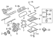
2004 Ford E-150 Intake Manifold Part Number: 4C2Z-9424-CA
Product Specifications- Other Name: Manifold Assembly - Inlet; Lower Manifold
- Base No.: 9424
- Item Weight: 21.40 Pounds
- Item Dimensions: 22.1 x 19.8 x 12.9 inches
- Condition: New
- Fitment Type: Direct Replacement
- SKU: 4C2Z-9424-CA
- Warranty: This genuine part is guaranteed by Ford's factory warranty.


2004 Ford E-150 Intake Manifold, Lower Part Number: 4L3Z-9424-AA
Product Specifications- Other Name: Manifold Assembly - Inlet; Engine Intake Manifold, Lower
- Manufacturer Note: Lower. Includes 6N041 insulator cover
- Position: Lower
- Base No.: 9424
- Item Weight: 7.90 Pounds
- Item Dimensions: 20.4 x 15.2 x 10.4 inches
- Condition: New
- Fitment Type: Direct Replacement
- SKU: 4L3Z-9424-AA
- Warranty: This genuine part is guaranteed by Ford's factory warranty.

2004 Ford E-150 Intake Manifold, Upper Part Number: 3L3Z-9424-DA
Product Specifications- Other Name: Manifold Assembly - Inlet; Engine Intake Manifold, Upper; Intake Plenum
- Manufacturer Note: Upper, FROM 12/9/2002
- Position: Upper
- Base No.: 9424
- Item Weight: 15.80 Pounds
- Item Dimensions: 19.9 x 16.9 x 10.0 inches
- Condition: New
- Fitment Type: Direct Replacement
- SKU: 3L3Z-9424-DA
- Warranty: This genuine part is guaranteed by Ford's factory warranty.
2004 Ford E-150 Intake Manifold
If you're seeking quality and affordability, look no further than our extensive inventory of genuine 2004 Ford E-150 Intake Manifold available at FordPartsDeal.com. You can confidently purchase our OEM 2004 Ford E-150 Intake Manifold as they are supported by the manufacturer's warranty and our hassle-free return policy, alongside the benefit of our fast delivery service.
2004 Ford E-150 Intake Manifold Parts Q&A
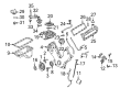
- Q: How to service the intake manifold on a 4.6L engine on 2004 Ford E-150?A: The first step for servicing an intake manifold on a 4.6L engine involves disconnecting the battery ground cable together with engine cover removal. Removal of the fuel hose spring lock coupling allows engineers to drain the cooling system. You can access the mass airflow sensor electrical connector after loosening the engine air cleaner (ACL) through removing its four bolts and releasing the clamp. The service begins with disconnecting the MAF sensor connector and removing the air cleaner lid followed by disconnecting two hoses to remove the air cleaner outlet pipe after loosening its clamp. The procedure begins by compressing and sliding the hose clamp of the upper radiator hose followed by removing the accelerator cable snow shield and disconnecting the throttle body control linkage through removal of the accelerator cable and speed control actuator cable and throttle control return spring. Use a socket set to remove the accelerator cable bracket bolts and proceed to disconnect the throttle position (TP) sensor connector as well as the differential pressure feedback exhaust gas recirculation (EGR) sensor electrical connector and vacuum hoses from the EGR valve tube. The technician needs to detach the exhaust manifold from the EGR valve tube while disconnecting the EGR vacuum regulator solenoid electrical connector and vacuum hoses and also removing the brake booster vacuum hose alongside the PCV valve hose and coolant hose and IAC valve fresh air hose. Start by taking out the two purge valve nuts from the evaporative emission canister while moving it out of the way followed by disconnecting the vacuum connector of EGR valve and IAC valve electric connections. First disconnect all coolant hoses together with the emissions tube and remove the throttle body including adapter assembly through four bolts and throw away the throttle body adapter gasket. Detach eight wire connectors that supply electricity for each plug coil then identify eight fuel injection wire connectors before you remove the ignition coils as well as the generator bracket's supporting bolts. The removal process starts with disconnecting the vacuum hose and electrical connector from the fuel pressure sensor followed by removing the thermostat housing and thermostat along with its O-ring seal. After that the assembly contains nine bolts that need to be removed to detach the intake manifold. Steal the intake manifold after disconnecting the intake manifold tuning valve electrical connector and discard the gaskets and examine the assembly for damage. The installation process starts by cleaning all sealing surfaces with a plastic scraper then you should position new intake manifold gaskets before you loosely install the upper intake manifold using nine bolts. After installing the thermostat that includes a new O-ring seal, begin tightening the thermostat housing bolts which should be done following the same sequence as the intake manifold bolts in two rounds starting at 2 Nm (18 inch lbs.) and finishing at 25 Nm (18 ft. lbs.). First install the generator upper support bracket and then connect its vacuum hose and fuel pressure sensor electrical connector. Finally mount the eight ignition coils and bolts. First install the throttle body adapter assembly with a new throttle body adapter gasket in position followed by electrical connector connecting of eight coil-on-plug electrical connectors and eight fuel injector electrical connectors. You must secure the coolant hoses together with the emissions tube and after that connect the IAC valve electrical connector and EGR valve vacuum connector. The service technician should install the evaporative emission canister purge valve along with its bracket while attaching all necessary vacuum hoses which include those for the brake booster and PCV valve and coolant and IAC fresh air. The EGR vacuum regulator solenoid electrical connector, together with vacuum hoses, should be connected. Additionally install the exhaust manifold to EGR valve tube before you hand-tighten and wrench the fittings to 40 Nm (30 ft. lbs.). Complete the installation by connecting the differential pressure feedback EGR sensor vacuum hoses, electrical connector and repositioning the fuel hose spring lock coupling as well as TP sensor electrical connector. Determine the placement of the accelerator cable bracket then connect the throttle body control linkage followed by installation of the accelerator cable along with the speed control actuator cable and the throttle control return spring. Mount the accelerator cable snow shield while installing the upper radiator hose along with the air cleaner outlet pipe and tighten the clamp. Start by connecting the two hoses to the air cleaner outlet pipe followed by installing the MAF sensor and the ACL positioning steps and then install with four bolts and clamp tightening before installing the interior engine cover and reconnecting the battery ground cable ends with filling and bleeding the engine cooling system.
Related 2004 Ford E-150 Parts
 2004 Ford E-150 Air Duct
 2004 Ford E-150 Air Filter
 2004 Ford E-150 Air Filter Box
 2004 Ford E-150 Fuel Filler Hose
 2004 Ford E-150 Fuel Filler Neck
 2004 Ford E-150 Fuel Filter
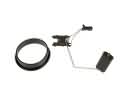 2004 Ford E-150 Fuel Level Sensor
 2004 Ford E-150 Fuel Tank
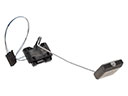 2004 Ford E-150 Fuel Tank Sending Unit
 2004 Ford E-150 Fuel Tank Strap
 2004 Ford E-150 Gas Cap
 2004 Ford E-150 Intake Manifold Gasket