FordParts
My Garage
My Account
Cart
OEM 2004 Ford F-250 Super Duty Intake Manifold
Engine Intake Manifold- Select Vehicle by Model
- Select Vehicle by VIN
Select Vehicle by Model
orMake
Model
Year
Select Vehicle by VIN
For the most accurate results, select vehicle by your VIN (Vehicle Identification Number).
5 Intake Manifolds found


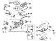
2004 Ford F-250 Super Duty Intake Manifold, Upper Part Number: 2C3Z-9424-BA
$520.97 MSRP: $765.00You Save: $244.03 (32%)Ships in 1-3 Business DaysProduct Specifications- Other Name: Manifold Assembly - Inlet; Engine Intake Manifold, Upper; Upper Manifold
- Manufacturer Note: Upper. includes heater inlet tube xl1z-18599-aa
- Position: Upper
- Base No.: 9424
- Item Weight: 28.20 Pounds
- Item Dimensions: 10.0 x 24.4 x 20.6 inches
- Condition: New
- Fitment Type: Direct Replacement
- SKU: 2C3Z-9424-BA
- Warranty: This genuine part is guaranteed by Ford's factory warranty.

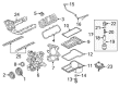
2004 Ford F-250 Super Duty Intake Manifold, Lower Part Number: 4C3Z-9424-AA
$222.46 MSRP: $326.67You Save: $104.21 (32%)Ships in 1-2 Business DaysProduct Specifications- Other Name: Manifold Assembly - Inlet; Engine Intake Manifold, Lower; Lower Manifold
- Manufacturer Note: Lower. Includes 9461 gaskets
- Position: Lower
- Replaces: YC2Z-9424-AA
- Base No.: 9424
- Item Weight: 9.50 Pounds
- Item Dimensions: 8.2 x 22.2 x 10.8 inches
- Condition: New
- Fitment Type: Direct Replacement
- SKU: 4C3Z-9424-AA
- Warranty: This genuine part is guaranteed by Ford's factory warranty.


2004 Ford F-250 Super Duty Intake Manifold Part Number: 4C2Z-9424-CA
Product Specifications- Other Name: Manifold Assembly - Inlet; Lower Manifold
- Base No.: 9424
- Item Weight: 21.40 Pounds
- Item Dimensions: 22.1 x 19.8 x 12.9 inches
- Condition: New
- Fitment Type: Direct Replacement
- SKU: 4C2Z-9424-CA
- Warranty: This genuine part is guaranteed by Ford's factory warranty.

2004 Ford F-250 Super Duty Lower Manifold Part Number: 4C3Z-9424-E
Product Specifications- Other Name: Kit - Manifold Hardware; Intake Manifold
- Replaces: 4C3Z-9424-C, 4C3Z-9424-D
- Item Weight: 20.50 Pounds
- Condition: New
- Fitment Type: Direct Replacement
- SKU: 4C3Z-9424-E
- Warranty: This genuine part is guaranteed by Ford's factory warranty.


2004 Ford F-250 Super Duty Lower Manifold Part Number: 3C3Z-9424-AJ
Product Specifications- Other Name: Kit - Manifold Hardware; Intake Manifold
- Manufacturer Note: KIT INTAKE MANIFOLD
- Replaces: 3C3Z-9424-AE, 3C3Z-9424-AH
- Item Weight: 20.70 Pounds
- Condition: New
- Fitment Type: Direct Replacement
- SKU: 3C3Z-9424-AJ
- Warranty: This genuine part is guaranteed by Ford's factory warranty.
2004 Ford F-250 Super Duty Intake Manifold
If you're seeking quality and affordability, look no further than our extensive inventory of genuine 2004 Ford F-250 Super Duty Intake Manifold available at FordPartsDeal.com. You can confidently purchase our OEM 2004 Ford F-250 Super Duty Intake Manifold as they are supported by the manufacturer's warranty and our hassle-free return policy, alongside the benefit of our fast delivery service.
2004 Ford F-250 Super Duty Intake Manifold Parts Q&A
- Q: How to service and repair the intake manifold on 2004 Ford F-250 Super Duty?A: The first step for servicing and repairing the intake manifold includes safety precautions which require that you stay away from fuel components with open flames or smoking areas because flammable mixtures will be active. First empty fuel pressure from the system then disconnect the battery cable and drain your engine cooling fluid. First disconnect the radiator outlet tube and generate then remove all fuel lines from the components. First disconnect the water outlet hose by compressing and sliding its hose clamp before removing the accelerator cable splash shield. Then disconnect accelerator and speed control cables, eliminate the return spring, move the accelerator cable bracket to a separate location. The engineer should first detach the cables and bracket retaining bolts followed by removing the Positive Crankcase Valve (PCV) tube, vacuum lines and heated PCV coolant hoses. Step one requires removing the bolt to position away the right-hand radio ignition interference capacitor and disconnecting the vacuum line before removing five right-hand fuel injector and ignition coil electrical connectors with the Idle Air Control (IAC) motor electrical connector and bypass hose. Remove the heater hose then take off the Throttle Body adapter together with its press-in-place gasket. Disconnect the five left-hand fuel injector and ignition coil connectors, Engine Coolant Temperature (ECT) sensor electrical connectors along with ignition coils by removing their 10 bolts. To begin the procedure disconnect the vacuum connector from the fuel pressure regulator while removing the bolt which positions the left-hand ignition radio interference capacitor aside and disconnecting the Cylinder Head Temperature (CHT) sensor. Remove the water thermostat together with its housing before you take out all bolts from the upper intake manifold to discard the gaskets and remove the intake manifold. Cleansing operations on mating surfaces should avoid abrasive tools during the process of removing the 10 bolts separating upper from lower intake manifolds. The installation process should start by placing the lower intake manifold onto the upper intake manifold then installing its 10 bolts loosely before tightening them in two sets of intervals beginning at 2 Nm (18 inch lbs.) and ending at 10 Nm (89 inch lbs.). Installation requires the positioning of the water thermostat and housing before upper intake manifold application along with new gaskets followed by bolt tightening in two steps at 2 Nm (18 inch lbs) then 25 Nm (18 ft. lbs). Replace the fuel line O-ring seals with new seals. Clean the engine oil and use it to lubricate the seals. Install them after application of lubrication. Connect the fuel lines along with CHT sensor electrical connector and left-hand radio ignition interference capacitor electrical connector. Install the ignition coils by threading in the ten bolts after connecting three elements together: the fuel injection supply manifold, ECT sensor electrical connector and vacuum line. Install the TB adapter with new gasket and tighten four bolts in two stages starting from 9 Nm (80 inch lbs.) and another 90° sequence. The installation requires connections of coolant hose and IAC motor bypass hose and connector and five right-hand fuel injector and ignition coil connectors. The vacuum lines need to be connected while installing the right-hand radio ignition interference capacitor and adding the PCV tube and vacuum lines and heated PCV coolant hoses. After installing the accelerator bracket along with its bolts the technician must connect the accelerator cables to speed control mechanisms alongside return springs before installing the accelerator cable splash shield. The procedure involves attaching the engine water outlet hose before clamping the hose followed by generator installation combined with air cleaner outlet tube and final steps of reconnecting the battery ground cable and cooling system filling and bleeding.
Related 2004 Ford F-250 Super Duty Parts
 2004 Ford F-250 Super Duty Air Duct
 2004 Ford F-250 Super Duty Air Filter
 2004 Ford F-250 Super Duty Fuel Filler Neck
 2004 Ford F-250 Super Duty Fuel Filter
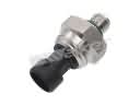 2004 Ford F-250 Super Duty Fuel Pressure Sensor
 2004 Ford F-250 Super Duty Fuel Pump
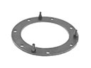 2004 Ford F-250 Super Duty Fuel Pump Gasket
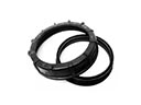 2004 Ford F-250 Super Duty Fuel Pump Seal
 2004 Ford F-250 Super Duty Fuel Pump Tank Seal
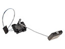 2004 Ford F-250 Super Duty Fuel Tank Sending Unit
 2004 Ford F-250 Super Duty Fuel Tank Strap
 2004 Ford F-250 Super Duty Intake Manifold Gasket