FordParts
My Garage
My Account
Cart
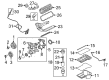
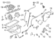
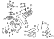
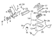
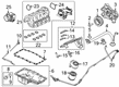
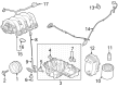
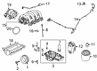
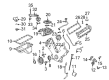
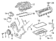
OEM Ford F-250 Super Duty Intake Manifold
Engine Intake Manifold- Select Vehicle by Model
- Select Vehicle by VIN
Select Vehicle by Model
orMake
Model
Year
Select Vehicle by VIN
For the most accurate results, select vehicle by your VIN (Vehicle Identification Number).
32 Intake Manifolds found


Ford F-250 Super Duty Intake Manifold Part Number: 5C3Z-9424-CRM
$1188.30 MSRP: $1783.33You Save: $595.03 (34%)


Ford F-250 Super Duty Intake Manifold, Lower Part Number: FC3Z-9424-A
$236.58 MSRP: $368.50You Save: $131.92 (36%)Ships in 1-2 Business Days


Ford F-250 Super Duty Intake Manifold, Lower Part Number: BC3Z-9424-C
$259.69 MSRP: $381.33You Save: $121.64 (32%)Ships in 1-3 Business Days

Ford F-250 Super Duty Intake Manifold Part Number: 9L3Z-9424-H
$301.91 MSRP: $443.33You Save: $141.42 (32%)


Ford F-250 Super Duty Intake Manifold Part Number: 2L1Z-9424-AA
$324.61 MSRP: $476.67You Save: $152.06 (32%)


Ford F-250 Super Duty Intake Manifold, Upper Part Number: 2C3Z-9424-BA
$520.97 MSRP: $765.00You Save: $244.03 (32%)Ships in 1-3 Business Days
Ford F-250 Super Duty Intake Manifold Part Number: HC3Z-9424-G
$717.75 MSRP: $1063.33You Save: $345.58 (33%)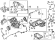
Ford F-250 Super Duty Intake Manifold Part Number: LC3Z-9424-E
$762.75 MSRP: $1130.00You Save: $367.25 (33%)Ships in 1-3 Business DaysFord F-250 Super Duty Intake Manifold, Upper Part Number: 9C2Z-9424-A
$2965.50 MSRP: $4393.33You Save: $1427.83 (33%)
Ford F-250 Super Duty Intake Manifold Part Number: PC3Z-9424-B
$138.55 MSRP: $201.67You Save: $63.12 (32%)Ships in 1-2 Business Days
Ford F-250 Super Duty Intake Manifold, Upper Part Number: GC4Z-9424-A
$116.79 MSRP: $170.00You Save: $53.21 (32%)Ford F-250 Super Duty Intake Manifold, Lower Part Number: LC3Z-9424-C
$172.90 MSRP: $251.67You Save: $78.77 (32%)Ships in 1-3 Business Days
Ford F-250 Super Duty Intake Manifold Part Number: LC3Z-9424-A
$221.33 MSRP: $325.00You Save: $103.67 (32%)Ships in 1-3 Business Days
Ford F-250 Super Duty Intake Manifold, Lower Part Number: 4C3Z-9424-AA
$209.72 MSRP: $326.67You Save: $116.95 (36%)Ships in 1-2 Business DaysFord F-250 Super Duty Intake Manifold, Upper Part Number: LC3Z-9424-B
$329.15 MSRP: $483.33You Save: $154.18 (32%)Ships in 1-3 Business Days
Ford F-250 Super Duty Intake Manifold Part Number: HC3Z-9424-A
$409.74 MSRP: $601.67You Save: $191.93 (32%)Ships in 1-2 Business DaysFord F-250 Super Duty Lower Manifold Part Number: 5C3Z-9424-CA
$409.74 MSRP: $601.67You Save: $191.93 (32%)Ships in 1-2 Business Days
Ford F-250 Super Duty Intake Manifold Part Number: HC3Z-9424-K
$664.88 MSRP: $985.00You Save: $320.12 (33%)Ships in 1-3 Business Days


Ford F-250 Super Duty Intake Manifold Part Number: 5L1Z-9424-A


Ford F-250 Super Duty Intake Manifold Part Number: 4C2Z-9424-CA
| Page 1 of 2 |Next >
1-20 of 32 Results
Ford F-250 Super Duty Intake Manifold
OEM Intake Manifold boasts unmatched quality. Each part goes through full quality checks. They adhere to Ford's official factory standards. These steps remove flaws and inconsistencies. So you can get Intake Manifold with long life and a perfect fit. Come to our website and find genuine Ford F-250 Super Duty parts. We keep a wide inventory of OEM F-250 Super Duty parts at the highly affordable prices. It's easy to search, compare, and pick what you need. You'll love the clear info and simple checkout. We offer top-rated customer service, and we reply fast. We also ship promptly to ensure your order arrives on time.
The Ford F-250 Super Duty Intake Manifold is an essential part regarded as dependable and effective in boosting the F-250 Super Duty models' engine performance. This Intake Manifold really channels the air or air/fuel mixture to the cylinder head intake port, which further boosts the engine power and efficiency. Intended for a range of engines, carbureted and fuel injected F-250 Super Duty Intake Manifold has grown from cast iron & aluminum to light plastic composites, improving fuel and cooling. For instance, complex designs as variable length intake manifolds (VLIM) go even further to increase air intake, with the use of principles as the Venturi effect. Ford F-250 Super Duty is produced in different models, Regular Cab, Super Cab, and Crew Cab which makes it possible for it to fit any task. The design on Intake Manifold also enhances the safety as well as it provides responsiveness of the engine as well as lower emission level. Additional characteristics including the coolant passages and exhaust crossovers improve the fuel evaporation and hence makes the Ford F-250 Super Duty Intake Manifold quite unique in the automobile industry. Great as a performance part, the Ford F-250 Super Duty Intake Manifold is also a sturdy piece that adds to the veracity of the vehicle which makes it very useful to any serious user of a truck.
Ford F-250 Super Duty Intake Manifold Parts and Q&A
- Q: How to install the intake manifold and its associated components on Ford F-250 Super Duty?A:The 10 bolts should be loosely installed onto the interface between the upper intake manifold and lower intake manifold before their proper positioning. Begin bolt tightening process at 2 Nm (18 inch lbs.) and finish at 10 Nm (89 inch lbs.) after performing bolts according to the guided sequence. Begin fuel injector supply manifold installation by fitting it correctly then using seven bolts for securing. Start with placing the water Thermostat along with the housing before installing the upper intake manifold through gasket positioning and bolt placement without tightness. The specified bolt sequence must be followed when tightening them in two stages starting at 2 Nm (18 inch lbs.) then moving to 25 Nm (18 ft. lbs.). The procedure requires attachment of the cylinder head temperature sensor as well as installing the LH radio interference capacitor followed by fuel line and vacuum line installation to the fuel injection supply manifold. Position the 10 Ignition Coils on their designated spots then fasten them with their respective 10 bolts. Secure the generator while connecting its electrical connector to the water temperature indicator sending unit. Attach all five connectors which power the LH fuel injectors and connect the five LH ignition coils. Position the EVR solenoid bracket then fasten it with its installation bolts. The throttle body adapter requires installation using a new gasket while tightening four bolts to 9 Nm (80 inch lbs.) in the first stage and adding an additional 85-95 degrees during the second stage of bolt tightening. Attaching the EVR solenoid vacuum and electrical connectors plus the EGR valve vacuum line as well as the EGR valve-to-exhaust manifold tube requires initial fitting hand-tightening then subsequent upper and lower fitting tightening to 40 - 60 Nm (30 - 44 ft. lbs.). Installation of the EGR transducer bracket should be followed by vacuum line installation and connection of the transducer and throttle position sensor sensors. The heater hose along with idle air control motor bypass hose and connector along with five RH fuel injector electrical connectors and five RH ignition coil connectors need to be connected. The RH radio interference capacitor needs installation with its bolt after connecting the vacuum line. Fix all vacuum lines into place for the Brake Booster and engine control sensor wiring harness as well as route PCV vacuum and coolant hoses. The first step is to install the accelerator bracket while using bolts as fasteners followed by the installation process of Accelerator Cables and speed control cables and the return spring. Mount the accelerator cable splash shield and fit in the air cleaner outlet tube. The water outlet hose must be connected along with its hose clamp installation while filling the cooling system and completing Battery Cable grounding.
- Q: How to remove and replace the intake manifold on Ford F-250 Super Duty?A:The first step when removing the intake manifold requires avoiding any sources of fuel proximity to smoking or open flames because this area contains flammable combinations. The procedure needs you to reduce fuel system pressure prior to unfastening any fuel tubes. First disconnect the fuel supply spring lock coupling from the Fuel Rail before draining the cooling system and removing the generator operation. The Air Cleaner (ACL) outlet pipe should be taken off first along with disconnecting the upper radiator hose from the Thermostat Housing after detaching the heater coolant hose and PCV coolant hose from the engine coolant crossover assembly. Disconnect the electrical connectors of the IMRC actuator along with the fuel rail pressure sensor, temperature sensor and vacuum connector and 10 Fuel Injectors. Start by disconnecting the quick connect coupling of the PCV tube followed by the Evaporative Emission tube coupling attached to the intake manifold and finally detach the crankcase ventilation tube. You should remove the wiring and vacuum harness retainers from the intake manifold back while also detaching engine vacuum hose links and cutting the 2 heated PCV coolant hoses. First disconnect the Throttle Position (TP) sensor connector together with the Electronic Throttle Control (ETC) electrical connector. Then remove the 12 bolts from the intake manifold. Clean all surface areas with a plastic scraper combined with silicone remover which leads to discarding old gaskets. Inspection for metal debris in the intake manifold needs to be performed after engine repairs for upper engine failure and replacement should occur when such debris is found. Place the intake manifold onto position using 10 new gaskets followed by installing the engine coolant crossover manifold assembly with 2 new gaskets along with its 3 bolts which should have a torque of 10 Nm (89 lb-in). The installation process for intake manifold bolts should follow steps one and two: initiate with 2 Nm (18 lb-in) and complete with 10 Nm (89 lb-in). Reinstall the TP sensor electrical connector and the ETC electrical connector followed by reattachment of engine wiring harness position retainers together with reconnection of engine vacuum hoses and wiring harness retainers while reinstalling both PCV and EVAP tube quick connect couplings along with installation of the 2 heated PCV coolant hoses into position. Secure the IMRC actuator electrical connector followed by connecting the vacuum and electrical connectors for the fuel rail pressure and temperature sensors and the 10 fuel injector electrical connectors and vacuum connector. You must perform the following last procedures: connect the fuel supply spring lock coupling along with the heater coolant hose, heated PCV coolant hose, upper radiator hose, crankcase ventilation tube, reinstall the generator and ACL outlet pipe and fill the engine cooling system before bleeding it.


Related Ford F-250 Super Duty Parts
 Ford F-250 Super Duty Air Filter
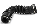 Ford F-250 Super Duty Air Intake Hose
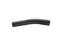 Ford F-250 Super Duty Fuel Filler Hose
 Ford F-250 Super Duty Fuel Pressure Sensor
 Ford F-250 Super Duty Fuel Pump
 Ford F-250 Super Duty Fuel Pump Tank Seal
 Ford F-250 Super Duty Fuel Sending Unit
 Ford F-250 Super Duty Fuel Tank
 Ford F-250 Super Duty Fuel Tank Lock Ring
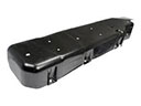 Ford F-250 Super Duty Fuel Tank Skid Plate
 Ford F-250 Super Duty Fuel Tank Strap
 Ford F-250 Super Duty Fuel Tank Vent Valve