FordParts
My Garage
My Account
Cart
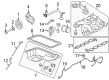
OEM 2004 Ford Mustang Intake Manifold
Engine Intake Manifold- Select Vehicle by Model
- Select Vehicle by VIN
Select Vehicle by Model
orMake
Model
Year
Select Vehicle by VIN
For the most accurate results, select vehicle by your VIN (Vehicle Identification Number).
5 Intake Manifolds found


2004 Ford Mustang Intake Manifold Part Number: 1W7Z-9424-AB
$334.83 MSRP: $491.67You Save: $156.84 (32%)Product Specifications- Other Name: Manifold Assembly - Inlet
- Manufacturer Note: One Piece Design
- Replaced by: PU7Z-9424-A
- Base No.: 9424
- Item Weight: 17.00 Pounds
- Item Dimensions: 21.0 x 18.4 x 12.5 inches
- Condition: New
- Fitment Type: Direct Replacement
- SKU: 1W7Z-9424-AB
- Warranty: This genuine part is guaranteed by Ford's factory warranty.

2004 Ford Mustang Intake Manifold, Lower Part Number: YR3Z-9424-BA
Product Specifications- Other Name: Manifold Assembly - Inlet
- Position: Lower
- Base No.: 9424
- Item Weight: 9.10 Pounds
- Item Dimensions: 15.8 x 16.7 x 14.3 inches
- Condition: New
- Fitment Type: Direct Replacement
- SKU: YR3Z-9424-BA
- Warranty: This genuine part is guaranteed by Ford's factory warranty.

2004 Ford Mustang Intake Manifold, Upper Part Number: XR3Z-9424-AA
Product Specifications- Other Name: Manifold Assembly - Inlet
- Position: Upper
- Base No.: 9424
- Item Weight: 12.40 Pounds
- Item Dimensions: 16.1 x 17.2 x 14.3 inches
- Condition: New
- Fitment Type: Direct Replacement
- SKU: XR3Z-9424-AA
- Warranty: This genuine part is guaranteed by Ford's factory warranty.

2004 Ford Mustang Intake Manifold, Upper Part Number: 2R3Z-9424-EB
Product Specifications- Other Name: Manifold Assembly - Inlet
- Position: Upper
- Replaces: 2R3Z-9424-EA
- Base No.: 9424A
- Item Weight: 17.00 Pounds
- Item Dimensions: 16.3 x 17.1 x 14.3 inches
- Condition: New
- Fitment Type: Direct Replacement
- SKU: 2R3Z-9424-EB
- Warranty: This genuine part is guaranteed by Ford's factory warranty.

2004 Ford Mustang Intake Manifold, Lower Part Number: 1R3Z-9424-BB
Product Specifications- Other Name: Manifold Assembly - Inlet
- Position: Lower
- Base No.: 9424B
- Item Weight: 19.70 Pounds
- Item Dimensions: 11.8 x 4.1 x 22.3 inches
- Condition: New
- Fitment Type: Direct Replacement
- SKU: 1R3Z-9424-BB
- Warranty: This genuine part is guaranteed by Ford's factory warranty.
2004 Ford Mustang Intake Manifold
If you're seeking quality and affordability, look no further than our extensive inventory of genuine 2004 Ford Mustang Intake Manifold available at FordPartsDeal.com. You can confidently purchase our OEM 2004 Ford Mustang Intake Manifold as they are supported by the manufacturer's warranty and our hassle-free return policy, alongside the benefit of our fast delivery service.
2004 Ford Mustang Intake Manifold Parts Q&A
- Q: How to service and repair the upper intake manifold on 2004 Ford Mustang?A: You should start the repair process of the upper intake manifold by disconnecting the battery ground cable. Start by disconnecting the engine air cleaner outlet pipe before removing its vacuum hose and idle air control valve electrical connector. The service starts with disconnecting the throttle position sensor electrical connector and removing the evaporative emissions return tube and then disconnecting the accelerator and speed control cables from the throttle body cam. You should take out the bolts to set the accelerator cable bracket assembly to the side. The installation requires disconnecting all electrical and vacuum elements of the differential pressure feedback EGR system and the EGR vacuum regulator solenoid. The positive crankcase ventilation (PCV) tube together with all vacuum hoses need removal. Detach the ignition coil electrical connector along with the radio interference capacitor electrical connector and plug wires. Easier installation requires operators to mark the positions of the long and short bolts before they uninstall the upper intake manifold by removing its 12 bolts and throwing away the upper intake manifold gasket. After installation add a new upper intake manifold gasket before you restore the bolts according to the locations documented during unbolt removal. The installation process for the upper intake manifold involves two-step bolt tightening: a 10 Nm (89 inch lbs.) initial stage followed by rotating them by 90 degrees (1/4 turn). The service procedure begins with reconnection of the vacuum hose followed by installation of the ignition coil electrical connector and radio interference capacitor electrical connector and spark plug wires. Finish the procedure by reconnecting all vacuum hoses and PCV tube. A proper connection exists for both electrical wiring and vacuum lines of the differential pressure feedback EGR system and EGR vacuum regulator solenoid. Reposition the accelerator cable bracket before installing its bolts and restoring connections between throttle body cam and speed control and accelerator cables. The last steps require hooking up the EVAP return tube with the TP sensor electrical connector while you link the vacuum hose with the IAC valve electrical connector followed by reinstalling the engine air cleaner outlet pipe and reestablishing the battery ground cable.
Related 2004 Ford Mustang Parts
 2004 Ford Mustang Fuel Tank
 2004 Ford Mustang Air Filter
 2004 Ford Mustang Mass Air Flow Sensor
 2004 Ford Mustang Air Duct
 2004 Ford Mustang Air Filter Box
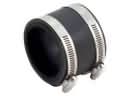 2004 Ford Mustang Air Intake Coupling
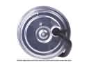 2004 Ford Mustang Cruise Control Servo
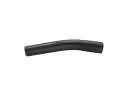 2004 Ford Mustang Fuel Filler Hose
 2004 Ford Mustang Fuel Pump Tank Seal
 2004 Ford Mustang Fuel Tank Sending Unit
 2004 Ford Mustang Fuel Tank Strap
 2004 Ford Mustang Idle Control Valve