FordParts
My Garage
My Account
Cart
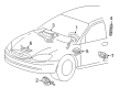
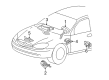
OEM 2004 Mercury Sable Clock Spring
Spiral Cable Clock Spring- Select Vehicle by Model
- Select Vehicle by VIN
Select Vehicle by Model
orMake
Model
Year
Select Vehicle by VIN
For the most accurate results, select vehicle by your VIN (Vehicle Identification Number).
2 Clock Springs found


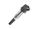
2004 Mercury Sable Clockspring Part Number: 4F1Z-14A664-AB
Product Specifications- Other Name: Cover And Contact Plate Assembly; Air Bag Clockspring
- Manufacturer Note: Atlanta and Chicago built, AFTER 12/17/03
- Replaces: 4F1Z-14A664-AA
- Base No.: 14A664
- Item Weight: 0.80 Pounds
- Item Dimensions: 8.4 x 6.0 x 2.9 inches
- Condition: New
- Fitment Type: Direct Replacement
- SKU: 4F1Z-14A664-AB
- Warranty: This genuine part is guaranteed by Ford's factory warranty.

2004 Mercury Sable Clockspring Part Number: 2F1Z-14A664-AA
Product Specifications- Other Name: Cover And Contact Plate Assembly; Air Bag Clockspring
- Manufacturer Note: Snap on type, Atlanta and Chicago built
- Base No.: 14A664
- Item Weight: 0.30 Pounds
- Item Dimensions: 6.4 x 6.2 x 2.9 inches
- Condition: New
- Fitment Type: Direct Replacement
- SKU: 2F1Z-14A664-AA
- Warranty: This genuine part is guaranteed by Ford's factory warranty.
2004 Mercury Sable Clock Spring
If you're seeking quality and affordability, look no further than our extensive inventory of genuine 2004 Mercury Sable Clock Spring available at FordPartsDeal.com. You can confidently purchase our OEM 2004 Mercury Sable Clock Spring as they are supported by the manufacturer's warranty and our hassle-free return policy, alongside the benefit of our fast delivery service.
2004 Mercury Sable Clock Spring Parts Q&A
- Q: What Precautions Should Be Taken When Servicing the Clock Spring Assembly to Ensure Air Bag System Safety on 2004 Mercury Sable?A: Wear safety glasses when working on the Clock Spring assembly to reduce the chances of injury during air bag deployment. Manufacture Live air bag modules are delicate; therefore, handle them with care and wash hands after opening, and damaged trim covers should be replaced. Returning a vehicle before ensuring that the SRS is working. Correctly remove and install parts, with connections being well-secured.
Related 2004 Mercury Sable Parts
 2004 Mercury Sable Ignition Coil
 2004 Mercury Sable Air Bag
 2004 Mercury Sable Air Bag Control Module
 2004 Mercury Sable Air Bag Sensor
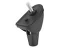 2004 Mercury Sable Antenna Base
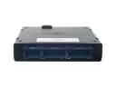 2004 Mercury Sable Body Control Module
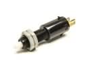 2004 Mercury Sable Brake Light Switch
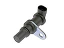 2004 Mercury Sable Crankshaft Position Sensor
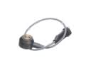 2004 Mercury Sable Knock Sensor
 2004 Mercury Sable Seat Belt
 2004 Mercury Sable Spark Plug Wire
 2004 Mercury Sable Window Switch