FordParts
My Garage
My Account
Cart
OEM 2005 Ford Crown Victoria Fuel Rail
Engine Fuel Rail- Select Vehicle by Model
- Select Vehicle by VIN
Select Vehicle by Model
orMake
Model
Year
Select Vehicle by VIN
For the most accurate results, select vehicle by your VIN (Vehicle Identification Number).
1 Fuel Rail found


2005 Ford Crown Victoria Fuel Rail Part Number: 5W7Z-9F792-AC
$312.13 MSRP: $458.33You Save: $146.20 (32%)Product Specifications- Other Name: Manifold Assembly - Fuel Supply
- Replaces: 5W7Z-9F792-AA
- Base No.: 9F792
- Item Weight: 2.20 Pounds
- Item Dimensions: 3.7 x 15.9 x 15.0 inches
- Condition: New
- Fitment Type: Direct Replacement
- SKU: 5W7Z-9F792-AC
- Warranty: This genuine part is guaranteed by Ford's factory warranty.
2005 Ford Crown Victoria Fuel Rail
If you're seeking quality and affordability, look no further than our extensive inventory of genuine 2005 Ford Crown Victoria Fuel Rail available at FordPartsDeal.com. You can confidently purchase our OEM 2005 Ford Crown Victoria Fuel Rail as they are supported by the manufacturer's warranty and our hassle-free return policy, alongside the benefit of our fast delivery service.
2005 Ford Crown Victoria Fuel Rail Parts Q&A
- Q: How to service and repair the fuel rail on 2005 Ford Crown Victoria?A: To maintain the fuel rail, do not put yourself at risk, unscrew the battery and depress the fuel pressure. Disassemble parts, such as throttle body, EGR system, de-wire and de-tube. Take out the fuel rail and injectors, O-rings change. Install with new seals, making sure to tighten all connections and parts.
Related 2005 Ford Crown Victoria Parts
 2005 Ford Crown Victoria Fuel Pump
 2005 Ford Crown Victoria Throttle Body
 2005 Ford Crown Victoria Air Filter
 2005 Ford Crown Victoria Air Filter Box
 2005 Ford Crown Victoria Cruise Control Switch
 2005 Ford Crown Victoria Fuel Filter
 2005 Ford Crown Victoria Fuel Injector
 2005 Ford Crown Victoria Fuel Pressure Sensor
 2005 Ford Crown Victoria Fuel Pump Gasket
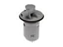 2005 Ford Crown Victoria Fuel Tank Vent Valve
 2005 Ford Crown Victoria Gas Cap
 2005 Ford Crown Victoria Mass Air Flow Sensor