FordParts
My Garage
My Account
Cart
OEM Ford Crown Victoria Fuel Rail
Engine Fuel Rail- Select Vehicle by Model
- Select Vehicle by VIN
Select Vehicle by Model
orMake
Model
Year
Select Vehicle by VIN
For the most accurate results, select vehicle by your VIN (Vehicle Identification Number).
4 Fuel Rails found


Ford Crown Victoria Fuel Rail Part Number: 5W7Z-9F792-AC
$312.13 MSRP: $458.33You Save: $146.20 (32%)
Ford Crown Victoria Fuel Rail Part Number: XW1Z-9F792-AA

Ford Crown Victoria Fuel Rail Part Number: 3W7Z-9F792-CD
Ford Crown Victoria Fuel Rail Part Number: 1W7Z-9F792-AA
Ford Crown Victoria Fuel Rail
OEM Fuel Rail boasts unmatched quality. Each part goes through full quality checks. They adhere to Ford's official factory standards. These steps remove flaws and inconsistencies. So you can get Fuel Rail with long life and a perfect fit. Come to our website and find genuine Ford Crown Victoria parts. We keep a wide inventory of OEM Crown Victoria parts at the highly affordable prices. It's easy to search, compare, and pick what you need. You'll love the clear info and simple checkout. We offer top-rated customer service, and we reply fast. We also ship promptly to ensure your order arrives on time.
Ford Crown Victoria Fuel Rail Parts and Q&A
- Q: How to service and repair the fuel rail on Ford Crown Victoria?A:Refrain from service or repair procedures on the fuel rail until all safety protocols are implemented because fuel components possess high flammability. Remove the ground cable of the battery and drain fuel system pressure to stop accidental fuel spattering. The technician must disconnect fuel tubes before taking out both the Throttle Body (TB) and exhaust gas recirculation (EGR) system module linked to the exhaust manifold tube. The service starts by disconnecting the Drive Belt accessory and unfastening the generator cable then disconnecting the connector along with the pin-type retainer and removing the mounting bracket bolts. If you want to separate the fuel charging wiring pin-type retainer from the crash bracket you have to first disconnect the vacuum tubes and electrical connector then remove the bolt and stud. Disconnection of the ground connector from the RH rear stud and the generator harness retainer from the LH front stud should be followed by disconnecting the eight fuel injector electrical connectors. The technician should detach the crankcase ventilation tube then separately unplug the vacuum tubes with electrical connectors from the evaporative emission (EVAP) Canister Purge Valve. Additionally disconnect the fuel rail pressure sensor including the temperature sensor and the vapor tubes with electrical connectors from the evaporative emission (EVAP) canister purge valve. The fuel rail removal begins with the uninstallation of four retaining studs that allows the fuel rail assembly to be extracted with its fuel injectors. Dispose the O-ring seals at this time. To install the fuel rail assembly use new O-ring seals from fuel-resistant materials while applying clean engine oil to the injectors before installation into the rail. Connect the fuel rail with the injectors by using an assembly method while tightening each fuel rail stud to 10 Nm (89 lb-in). After reinstalling the crash bracket along with its associated bolt and stud you need to attach the vacuum tubes and electrical connector. Begin by reconnecting the EVAP canister purge valve electrical connector followed by linking the two vapor tubes before proceeding with the vacuum and electrical connector of the fuel rail pressure and temperature sensor. Reinstall the fuel charging pin-type retainer to the crash bracket after connecting the crankcase ventilation tube along with eight fuel injector electrical connectors. The generator mounting bracket receives its reinstall and bolts achieve 10 Nm (89 lb-in) torque during tightening. Generator cable and electrical connector and harness pin-type retainer receive their respective reconnections. The last step involves attaching the RH rear stud to the ground connector while installing the generator harness location retainer to the LH front stud and keeping the EGR system module-to-exhaust manifold tube as well as the TB and fuel tubes in place and reconnecting the battery ground cable.

Related Ford Crown Victoria Parts
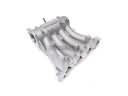 Ford Crown Victoria Intake Manifold
 Ford Crown Victoria Air Duct
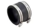 Ford Crown Victoria Air Intake Coupling
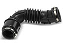 Ford Crown Victoria Air Intake Hose
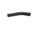 Ford Crown Victoria Fuel Filler Hose
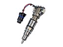 Ford Crown Victoria Fuel Injector
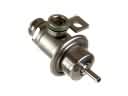 Ford Crown Victoria Fuel Pressure Regulator
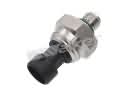 Ford Crown Victoria Fuel Pressure Sensor
 Ford Crown Victoria Fuel Pump Tank Seal
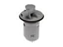 Ford Crown Victoria Fuel Tank Vent Valve
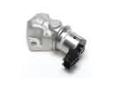 Ford Crown Victoria Idle Control Valve
 Ford Crown Victoria Mass Air Flow Sensor