FordParts
My Garage
My Account
Cart
OEM 2006 Ford Expedition Intake Manifold
Engine Intake Manifold- Select Vehicle by Model
- Select Vehicle by VIN
Select Vehicle by Model
orMake
Model
Year
Select Vehicle by VIN
For the most accurate results, select vehicle by your VIN (Vehicle Identification Number).
1 Intake Manifold found


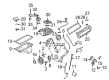
2006 Ford Expedition Intake Manifold Part Number: 5L1Z-9424-A
Product Specifications- Other Name: Manifold Assembly - Inlet; Engine Intake Manifold; Lower Manifold
- Replaces: 5L1Z-9424-AB
- Base No.: 9424
- Item Weight: 22.10 Pounds
- Item Dimensions: 23.5 x 19.4 x 15.8 inches
- Condition: New
- Fitment Type: Direct Replacement
- SKU: 5L1Z-9424-A
- Warranty: This genuine part is guaranteed by Ford's factory warranty.
2006 Ford Expedition Intake Manifold
If you're seeking quality and affordability, look no further than our extensive inventory of genuine 2006 Ford Expedition Intake Manifold available at FordPartsDeal.com. You can confidently purchase our OEM 2006 Ford Expedition Intake Manifold as they are supported by the manufacturer's warranty and our hassle-free return policy, alongside the benefit of our fast delivery service.
2006 Ford Expedition Intake Manifold Parts Q&A
- Q: How to service and repair the intake manifold on 2006 Ford Expedition?A: The first step for repair and maintenance of an intake manifold requires draining the cooling system. Start the procedure by letting fuel system pressure drain off first before unscrewing the fuel rail spring lock coupling of the fuel supply hose. The service requires generator and air cleaner disassembly followed by hose disconnection of the upper radiator to thermostat housing and heater coolant from coolant bypass tube. Unplug both the EVAP system evaporative tube and PCV system positive crankcase ventilation tube by removing their quick connection fittings. Remove the electrical connector of the fuel rail pressure and temperature sensor and the vacuum connector along with the eight fuel injector electrical connectors. The maintenance requires disconnecting the throttle position (TP) sensor alongside electronic acceleration control electrical connectors and heated PCV intake fitting electrical connector in addition to brake booster vacuum hose from the intake manifold vacuum tube. The ten intake manifold bolts should be removed while avoiding metal scrapers and abrasive tools on sealing surfaces by using a plastic scraping tool for surface cleansing and gasket disposal. The mechanic should disconnect the charge motion control valve (CMCV) electrical connector and the manifold vacuum tube from the valve cover stud as well as the support bracket and cylinder head temperature (CHT) sensor jumper harness electrical connector and left-hand and right-hand knock sensor (KS) electrical connectors. After disconnecting the engine wiring harness retainer from the CMCV stud the intake manifold can be removed by unfastening both the nut and stud. During installation verify that electrical connectors along with vacuum tubes do not prevent motion of the CMCV control rods. Attach new intake manifold gaskets to the position then install the coolant crossover through three new bolts which require 10 Nm (89 inch lbs.) torque value. The installation of intake manifold bolts requires a sequential order where you tighten them to 2 Nm (18 inch lbs.) first before advancing to 10 Nm (89 inch lbs.). Secure the engine wiring harness retainer to the CMCV stud and tighten it to 10 Nm (89 inch lbs.). Reconnect the CMCV electrical connector followed by CHT sensor jumper, left-hand and right-hand KS electrical connectors, manifold vacuum tube, brake booster vacuum hose, heated PCV intake fitting, TP sensor, electronic acceleration control connectors as well as the eight fuel injector electrical connectors. Next step is to place the fuel rail pressure and temperature sensor electrical connector and vacuum connector under the fuel supply spring lock coupling which needs to be connected to the fuel rail. Fasten the PCV tube and EVAP tube into the position where they meet the intake manifold. To complete the replacement process connect the generator and air cleaner then restore the coolant bypass to the heater coolant hose and the thermostat housing to the upper radiator hose while filling the engine cooling system appropriately.
Related 2006 Ford Expedition Parts
 2006 Ford Expedition Fuel Pump
 2006 Ford Expedition Air Filter
 2006 Ford Expedition Fuel Tank
 2006 Ford Expedition Gas Cap
 2006 Ford Expedition Mass Air Flow Sensor
 2006 Ford Expedition Throttle Body
 2006 Ford Expedition Air Filter Box
 2006 Ford Expedition Fuel Filler Neck
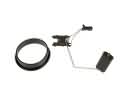 2006 Ford Expedition Fuel Level Sensor
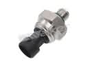 2006 Ford Expedition Fuel Pressure Sensor
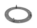 2006 Ford Expedition Fuel Pump Gasket
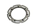 2006 Ford Expedition Fuel Tank Lock Ring