FordParts
My Garage
My Account
Cart
OEM 2006 Ford Focus Clutch Master Cylinder
- Select Vehicle by Model
- Select Vehicle by VIN
Select Vehicle by Model
orMake
Model
Year
Select Vehicle by VIN
For the most accurate results, select vehicle by your VIN (Vehicle Identification Number).
1 Clutch Master Cylinder found


2006 Ford Focus Master Cylinder Part Number: 1M5Z-7A543-AA
$50.10 MSRP: $71.67You Save: $21.57 (31%)Ships in 1-3 Business DaysProduct Specifications- Other Name: Master Cylinder Assembly; Clutch Master Cylinder; Brake Master Cylinder
- Manufacturer Note: ALL; MTX-75, IB5 and SVT w/Getrag 285 6-spd
- Replaces: YS4Z-7A543-AA
- Base No.: 7A543
- Item Weight: 0.90 Pounds
- Item Dimensions: 8.2 x 6.1 x 4.6 inches
- Condition: New
- Fitment Type: Direct Replacement
- SKU: 1M5Z-7A543-AA
- Warranty: This genuine part is guaranteed by Ford's factory warranty.
2006 Ford Focus Clutch Master Cylinder
If you're seeking quality and affordability, look no further than our extensive inventory of genuine 2006 Ford Focus Clutch Master Cylinder available at FordPartsDeal.com. You can confidently purchase our OEM 2006 Ford Focus Clutch Master Cylinder as they are supported by the manufacturer's warranty and our hassle-free return policy, alongside the benefit of our fast delivery service.
2006 Ford Focus Clutch Master Cylinder Parts Q&A
- Q: How to Ensure Proper Functioning of the Clutch Master Cylinder on 2006 Ford Focus?A: To maintain the clutch master cylinder, unconnect the battery and eliminate the brake liquid, and eliminate the central junction box. Disconnect the clutch lines, remove the instrument panel, install hydraulic lines on the cap, and cap hydraulic lines. Disassemble clutch pedal assembly and master cylinder and reattach and align switches. Top up, drain the system and replace the battery.
Related 2006 Ford Focus Parts
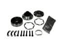 2006 Ford Focus CV Joint
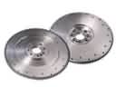 2006 Ford Focus Flywheel
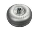 2006 Ford Focus Torque Converter
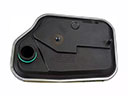 2006 Ford Focus Automatic Transmission Filter
 2006 Ford Focus Automatic Transmission Shift Levers
 2006 Ford Focus Automatic Transmission Shifter
 2006 Ford Focus Clutch Disc
 2006 Ford Focus Pressure Plate
 2006 Ford Focus Transmission Assembly
 2006 Ford Focus Transmission Pan