FordParts
My Garage
My Account
Cart
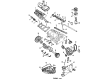
OEM 2006 Ford Taurus Timing Cover
Engine Timing Cover- Select Vehicle by Model
- Select Vehicle by VIN
Select Vehicle by Model
orMake
Model
Year
Select Vehicle by VIN
For the most accurate results, select vehicle by your VIN (Vehicle Identification Number).
1 Timing Cover found


2006 Ford Taurus Timing Cover Part Number: F5DZ-6019-A
Product Specifications- Other Name: Cover - Front; Engine Timing Cover; Front Cover
- Replaces: FODZ-6019-C, F3DZ-6019-A, F4DZ-6019-AFFV
- Base No.: 6019
- Item Weight: 4.40 Pounds
- Item Dimensions: 2.9 x 13.1 x 12.4 inches
- Condition: New
- Fitment Type: Direct Replacement
- SKU: F5DZ-6019-A
- Warranty: This genuine part is guaranteed by Ford's factory warranty.
2006 Ford Taurus Timing Cover
If you're seeking quality and affordability, look no further than our extensive inventory of genuine 2006 Ford Taurus Timing Cover available at FordPartsDeal.com. You can confidently purchase our OEM 2006 Ford Taurus Timing Cover as they are supported by the manufacturer's warranty and our hassle-free return policy, alongside the benefit of our fast delivery service.
2006 Ford Taurus Timing Cover Parts Q&A
- Q: How to service and repair the engine front timing cover to prevent engine failure on 2006 Ford Taurus?A: Organize service and repair operations of the engine front cover by maintaining cleanliness so that foreign substances cannot enter either the engine oil or coolant system to trigger failure. The first step must be to place the vehicle on a hoist where it should remain in neutral position. Start by disconnecting the battery ground cable and then extract the degas bottle from its position. First loosen the four bolts on the coolant pump pulley before removing the generator along with the crankshaft front seal. The servicing process starts by taking out the oil pan together with the nut and generator support bracket followed by the disconnecting of the lower heater and radiator hoses to the coolant pump. The service technician needs to remove the accessory drive belt idler pulley, accessory drive belt tensioner, and bolt, nut and A/C compressor bracket sequentially. The process begins by removing the four coolant pump pulley bolts until the coolant pump pulley can be detached. Next the technician follows up by removing the five bolts and five stud bolts to separate the engine front cover and coolant pump as an assembly, while front cover gasket remains for disposal. Begin by thoroughly cleaning all sealing surfaces before placing a new front cover gasket onto position as the first step for installing the engine front cover together with the coolant pump assembly. After applying thread sealant with PTFE to specified bolts, install and tighten five bolts and five stud bolts to 25 Nm (18 ft. lbs.) while finishing with the coolant pump pulley followed by four bolts that also need to be tightened to 25 Nm (18 ft. lbs.). Connect the A/C compressor bracket to 25 Nm (18 ft. lbs.) before putting on the accessory drive belt tensioner with idler pulley that requires tightening to 48 Nm (35 ft. lbs.). Finish radiator heater hose assembly at the coolant pump before attaching the generator support bracket with its nut and tightening both components to 25 Nm (18 ft. lbs.). The procedure requires replacement of the crankshaft front seal as well as the oil pan along with the generator. Reconnect the degas bottle before replacing the battery ground connection. Complete the cooling system filling procedure and perform bleeding operations.
Related 2006 Ford Taurus Parts
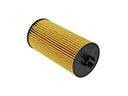 2006 Ford Taurus Oil Filter
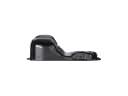 2006 Ford Taurus Oil Pan
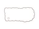 2006 Ford Taurus Oil Pan Gasket
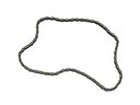 2006 Ford Taurus Timing Chain
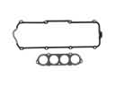 2006 Ford Taurus Valve Cover Gasket
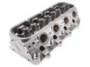 2006 Ford Taurus Cylinder Head
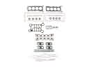 2006 Ford Taurus Cylinder Head Gasket
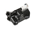 2006 Ford Taurus Engine Mount Bracket
 2006 Ford Taurus Exhaust Valve
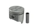 2006 Ford Taurus Piston
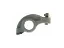 2006 Ford Taurus Rocker Arm
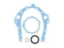 2006 Ford Taurus Timing Cover Gasket