FordParts
My Garage
My Account
Cart
OEM 2006 Mercury Monterey Clock Spring
Spiral Cable Clock Spring- Select Vehicle by Model
- Select Vehicle by VIN
Select Vehicle by Model
orMake
Model
Year
Select Vehicle by VIN
For the most accurate results, select vehicle by your VIN (Vehicle Identification Number).
1 Clock Spring found


2006 Mercury Monterey Clockspring Part Number: 5F2Z-14A664-AA
$278.68 MSRP: $409.22You Save: $130.54 (32%)Product Specifications- Other Name: Cover And Contact Plate Assembly; Air Bag Clockspring
- Replaces: 3F2Z-14A664-AA
- Base No.: 14A664
- Item Weight: 0.90 Pounds
- Item Dimensions: 8.4 x 6.2 x 3.1 inches
- Condition: New
- Fitment Type: Direct Replacement
- SKU: 5F2Z-14A664-AA
- Warranty: This genuine part is guaranteed by Ford's factory warranty.
2006 Mercury Monterey Clock Spring
If you're seeking quality and affordability, look no further than our extensive inventory of genuine 2006 Mercury Monterey Clock Spring available at FordPartsDeal.com. You can confidently purchase our OEM 2006 Mercury Monterey Clock Spring as they are supported by the manufacturer's warranty and our hassle-free return policy, alongside the benefit of our fast delivery service.
2006 Mercury Monterey Clock Spring Parts Q&A
- Q: What Safety Precautions Should Be Taken When Servicing the Clock Spring Assembly on 2006 Mercury Monterey?A: It is crucial to use safety glasses during Clock Spring assembly servicing because deployment risks will be minimized and live air bag modules should always be handled with the trim cover facing away from your body. Thorough handwashing is needed to eliminate remaining sodium hydroxide residue after release of air bag. air bag module connectors must never be probed and customers should obtain new air bag modules when trim covers become damaged or discolored instead of conducting repairs. A thorough inspection of SRS operation without faults should be performed to return the vehicle to its customer. The system dampening process must be completed while making sure wheels face forward before removing the wheel. You must remove the three screws on the steering column opening cover and then extract the trim panel while detaching both steering column reinforcement screws and lower cover. After removing the lower shroud screws of three and the tilt column handle, detach the lower steering column shroud. After setting the cylinder to RUN position use the tab to push and extract the lock cylinder. To reach the transceiver you need to uninstall the lower instrument cluster finish panel, upper steering column shroud, PATS transceiver screw, as well as the transceiver unit itself. Two strips of masking tape must be applied to the Clock Spring to stop unintentional rotation when it will be reused. Disconnect the Clock Spring electrical connectors before detaching the wire harness which allows you to slide off the Clock Spring from its position on the steering column. To install the Clock Spring maintain inner housing stability while rotating the rotor counterclockwise until resistance occurs then finish with a clockwise rotation of three turns. The Clock Spring should match the steering column position with its retainers snapping into correct placement after you also put the wire harness into the designated holders. The electrical connectors need to be connected while implementing the key-in-ignition warning switch and uninstalling the retaining pin for new Clock Springs. Reposition the PATS transceiver and its screw along with the upper shroud and lower instrument cluster finish panel before setting the ignition lock cylinder to its full position while maintaining alignment. Fasten the lower shroud after installing three lower screws and the tilt column handle and steering column reinforcement and two reinforcement screws must be tightened to 12 Nm (9 lb-ft). Circular installation ends with the lower opening cover tight with three lower screws at 12 Nm torque value and subsequent wheel attachment followed by system power restoration.
Related 2006 Mercury Monterey Parts
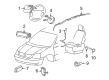
 2006 Mercury Monterey Air Bag
 2006 Mercury Monterey Air Bag Control Module
 2006 Mercury Monterey Air Bag Sensor
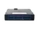 2006 Mercury Monterey Body Control Module
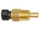 2006 Mercury Monterey Coolant Temperature Sensor
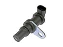 2006 Mercury Monterey Crankshaft Position Sensor
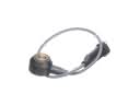 2006 Mercury Monterey Knock Sensor
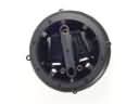 2006 Mercury Monterey Mirror Actuator
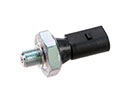 2006 Mercury Monterey Oil Pressure Switch
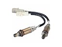 2006 Mercury Monterey Oxygen Sensors
 2006 Mercury Monterey Turn Signal Flasher
 2006 Mercury Monterey Turn Signal Switch