FordParts
My Garage
My Account
Cart
OEM 2007 Ford Freestar Clock Spring
Spiral Cable Clock Spring- Select Vehicle by Model
- Select Vehicle by VIN
Select Vehicle by Model
orMake
Model
Year
Select Vehicle by VIN
For the most accurate results, select vehicle by your VIN (Vehicle Identification Number).
1 Clock Spring found


2007 Ford Freestar Clockspring Part Number: 5F2Z-14A664-AA
$278.68 MSRP: $409.22You Save: $130.54 (32%)Product Specifications- Other Name: Cover And Contact Plate Assembly; Air Bag Clockspring
- Replaces: 3F2Z-14A664-AA
- Base No.: 14A664
- Item Weight: 0.90 Pounds
- Item Dimensions: 8.4 x 6.2 x 3.1 inches
- Condition: New
- Fitment Type: Direct Replacement
- SKU: 5F2Z-14A664-AA
- Warranty: This genuine part is guaranteed by Ford's factory warranty.
2007 Ford Freestar Clock Spring
If you're seeking quality and affordability, look no further than our extensive inventory of genuine 2007 Ford Freestar Clock Spring available at FordPartsDeal.com. You can confidently purchase our OEM 2007 Ford Freestar Clock Spring as they are supported by the manufacturer's warranty and our hassle-free return policy, alongside the benefit of our fast delivery service.
2007 Ford Freestar Clock Spring Parts Q&A
- Q: What Safety Precautions and Steps Should Be Followed When Servicing the Clock Spring Assembly on 2007 Ford Freestar?A: Use caution when servicing the Clock Spring assembly, wear safety glasses and use caution with air bag modules. Post-deployment hand washing and connector probing are to be avoided. Make sure that you check the fault of air bag system before handing in the vehicle. Dismantle and reassemble correctly, getting the Clock Spring aligned in the middle and all the parts properly fitted.
Related 2007 Ford Freestar Parts
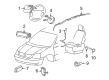
 2007 Ford Freestar Air Bag
 2007 Ford Freestar Air Bag Control Module
 2007 Ford Freestar Air Bag Sensor
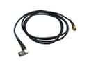 2007 Ford Freestar Antenna Cable
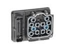 2007 Ford Freestar Brake Controller
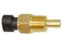 2007 Ford Freestar Coolant Temperature Sensor
 2007 Ford Freestar Door Jamb Switch
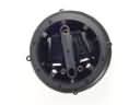 2007 Ford Freestar Mirror Actuator
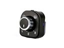 2007 Ford Freestar Mirror Switch
 2007 Ford Freestar Seat Belt
 2007 Ford Freestar Temperature Sender
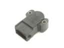 2007 Ford Freestar Throttle Position Sensor