FordParts
My Garage
My Account
Cart
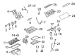
OEM 2007 Ford Mustang Intake Manifold
Engine Intake Manifold- Select Vehicle by Model
- Select Vehicle by VIN
Select Vehicle by Model
orMake
Model
Year
Select Vehicle by VIN
For the most accurate results, select vehicle by your VIN (Vehicle Identification Number).
4 Intake Manifolds found

2007 Ford Mustang Intake Manifold, Lower Part Number: 7R3Z-9424-AA
$259.92 MSRP: $381.67You Save: $121.75 (32%)Ships in 1-2 Business DaysProduct Specifications- Other Name: Manifold Assembly - Inlet; Engine Intake Manifold, Lower
- Position: Lower
- Base No.: 9424B
- Item Weight: 6.50 Pounds
- Item Dimensions: 20.8 x 10.2 x 4.2 inches
- Condition: New
- Fitment Type: Direct Replacement
- SKU: 7R3Z-9424-AA
- Warranty: This genuine part is guaranteed by Ford's factory warranty.


2007 Ford Mustang Intake Manifold Part Number: AR3Z-9424-C
$430.17 MSRP: $631.67You Save: $201.50 (32%)Product Specifications- Other Name: Manifold Assembly - Inlet; Engine Intake Manifold
- Replaces: AR3Z-9424-B, AR3Z-9424-A, 4R3Z-9424-EL, 7R3Z-9424-BA
- Item Weight: 21.60 Pounds
- Item Dimensions: 24.2 x 18.9 x 16.2 inches
- Condition: New
- Fitment Type: Direct Replacement
- SKU: AR3Z-9424-C
- Warranty: This genuine part is guaranteed by Ford's factory warranty.


2007 Ford Mustang Intake Manifold Part Number: 5R3Z-9424-BA
Product Specifications- Other Name: Manifold Assembly - Inlet; Engine Intake Manifold
- Base No.: 9424
- Item Weight: 11.80 Pounds
- Item Dimensions: 14.0 x 16.9 x 27.2 inches
- Condition: New
- Fitment Type: Direct Replacement
- SKU: 5R3Z-9424-BA
- Warranty: This genuine part is guaranteed by Ford's factory warranty.

2007 Ford Mustang Intake Manifold, Upper Part Number: 7R3Z-9424-CA
$618.75 MSRP: $916.67You Save: $297.92 (33%)Product Specifications- Other Name: Manifold Assembly - Inlet; Engine Intake Manifold, Upper
- Position: Upper
- Base No.: 9424A
- Item Weight: 22.00 Pounds
- Item Dimensions: 16.6 x 17.1 x 14.6 inches
- Condition: New
- Fitment Type: Direct Replacement
- SKU: 7R3Z-9424-CA
- Warranty: This genuine part is guaranteed by Ford's factory warranty.
2007 Ford Mustang Intake Manifold
If you're seeking quality and affordability, look no further than our extensive inventory of genuine 2007 Ford Mustang Intake Manifold available at FordPartsDeal.com. You can confidently purchase our OEM 2007 Ford Mustang Intake Manifold as they are supported by the manufacturer's warranty and our hassle-free return policy, alongside the benefit of our fast delivery service.
2007 Ford Mustang Intake Manifold Parts Q&A
- Q: How to service the intake manifold on 2007 Ford Mustang?A: In order to service the intake manifold, clean it to avoid engine failure. Un plug the battery ground cable and the air cleaner outlet pipe. Drain the renunciation system and de-hook different hoses and electrical connections. Take out the bolts holding the intake manifold, wash its sealing surfaces, and put everything back in the given order.
Related 2007 Ford Mustang Parts
 2007 Ford Mustang Fuel Tank
 2007 Ford Mustang Air Filter
 2007 Ford Mustang Fuel Filter
 2007 Ford Mustang Mass Air Flow Sensor
 2007 Ford Mustang Air Duct
 2007 Ford Mustang Air Filter Box
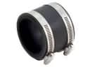 2007 Ford Mustang Air Intake Coupling
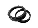 2007 Ford Mustang Fuel Pump Seal
 2007 Ford Mustang Fuel Pump Tank Seal
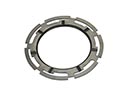 2007 Ford Mustang Fuel Tank Lock Ring
 2007 Ford Mustang Fuel Tank Sending Unit
 2007 Ford Mustang Fuel Tank Strap