FordParts
My Garage
My Account
Cart
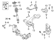
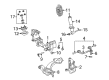
OEM 2007 Mercury Grand Marquis Control Arm
Suspension Arm- Select Vehicle by Model
- Select Vehicle by VIN
Select Vehicle by Model
orMake
Model
Year
Select Vehicle by VIN
For the most accurate results, select vehicle by your VIN (Vehicle Identification Number).
7 Control Arms found


2007 Mercury Grand Marquis Upper Control Arm, Front Driver Side Part Number: 6W1Z-3085-B
$92.93 MSRP: $152.91You Save: $59.98 (40%)Ships in 1 Business DayProduct Specifications- Other Name: Arm Assembly - Front Suspension; Front Left Upper Control Arm and Ball Joint Assembly.; Control Arm
- Manufacturer Note: L.H., Upper Control Arm only, stamped., FROM 12/05/05
- Position: Front Upper Driver Side
- Replaces: 6W1Z-3085-AA
- Base No.: 3084
- Item Weight: 6.10 Pounds
- Item Dimensions: 4.2 x 11.6 x 13.4 inches
- Condition: New
- Fitment Type: Direct Replacement
- SKU: 6W1Z-3085-B
- Warranty: This genuine part is guaranteed by Ford's factory warranty.

2007 Mercury Grand Marquis Upper Control Arm, Front Passenger Side Part Number: 6W1Z-3084-B
$92.93 MSRP: $152.91You Save: $59.98 (40%)Ships in 1-2 Business DaysProduct Specifications- Other Name: Arm Assembly - Front Suspension; Front Right Upper Control Arm and Ball Joint Assembly.; Control Arm
- Manufacturer Note: R.H., Upper Control Arm only, stamped., FROM 12/05/05
- Position: Front Upper Passenger Side
- Replaces: 6W1Z-3084-AA
- Base No.: 3084
- Item Weight: 5.50 Pounds
- Item Dimensions: 4.1 x 11.7 x 13.7 inches
- Condition: New
- Fitment Type: Direct Replacement
- SKU: 6W1Z-3084-B
- Warranty: This genuine part is guaranteed by Ford's factory warranty.
2007 Mercury Grand Marquis Upper Control Arm, Front Passenger Side Part Number: 6W1Z-3084-U
$89.73 MSRP: $147.64You Save: $57.91 (40%)Ships in 1-3 Business DaysProduct Specifications- Other Name: Arm Assembly - Front Suspension; Suspension Control Arm, Front Right Upper; Control Arm
- Position: Front Upper Passenger Side
- Replaces: 6W1Z-3084-R, 6W1Z-3084-T, 6W1Z-3084-S, MCSOE-35, 4W1Z-3084-RH, 5W1Z-3084-AA
- Item Weight: 8.20 Pounds
- Item Dimensions: 5.2 x 15.7 x 13.7 inches
- Condition: New
- Fitment Type: Direct Replacement
- SKU: 6W1Z-3084-U
- Warranty: This genuine part is guaranteed by Ford's factory warranty.

2007 Mercury Grand Marquis Lower Control Arm, Front Passenger Side Part Number: 6W1Z-3078-D
$262.79 MSRP: $341.82You Save: $79.03 (24%)Ships in 1-2 Business DaysProduct Specifications- Other Name: Arm Assembly - Front Suspension; Front Right Lower Control Arm and Ball Joint Assembly; Control Arm
- Manufacturer Note: R.H., standard suspension, without special packages, FROM 12/05/05
- Position: Front Lower Passenger Side
- Base No.: 3078
- Item Weight: 27.60 Pounds
- Item Dimensions: 5.2 x 15.6 x 26.3 inches
- Condition: New
- Fitment Type: Direct Replacement
- SKU: 6W1Z-3078-D
- Warranty: This genuine part is guaranteed by Ford's factory warranty.


 Product Specifications
- Other Name: Arm Assembly - Front Suspension; Front Left Lower Control Arm and Ball Joint Assembly.; Control Arm
- Position: Front Lower Driver Side
- Base No.: 3078
- Item Weight: 27.40 Pounds
- Item Dimensions: 4.6 x 15.6 x 26.0 inches
- Condition: New
- Fitment Type: Direct Replacement
- SKU: 6W7Z-3079-B
- Warranty: This genuine part is guaranteed by Ford's factory warranty.
 Product Specifications
- Other Name: Arm Assembly - Front Suspension; Front Right Lower Control Arm and Ball Joint Assembly; Control Arm
- Position: Front Lower Passenger Side
- Base No.: 3078
- Item Weight: 26.10 Pounds
- Item Dimensions: 4.7 x 15.7 x 26.3 inches
- Condition: New
- Fitment Type: Direct Replacement
- SKU: 6W7Z-3078-B
- Warranty: This genuine part is guaranteed by Ford's factory warranty.
- Product Specifications
- Other Name: Arm Assembly - Front Suspension; Front Left Lower Control Arm and Ball Joint Assembly.; Control Arm
- Manufacturer Note: L.H., standard suspension, without special packages, FROM 12/05/05
- Position: Front Lower Driver Side
- Base No.: 3078
- Item Weight: 26.30 Pounds
- Item Dimensions: 6.1 x 15.6 x 25.8 inches
- Condition: New
- Fitment Type: Direct Replacement
- SKU: 6W1Z-3079-D
- Warranty: This genuine part is guaranteed by Ford's factory warranty.
2007 Mercury Grand Marquis Control Arm
If you're seeking quality and affordability, look no further than our extensive inventory of genuine 2007 Mercury Grand Marquis Control Arm available at FordPartsDeal.com. You can confidently purchase our OEM 2007 Mercury Grand Marquis Control Arm as they are supported by the manufacturer's warranty and our hassle-free return policy, alongside the benefit of our fast delivery service.
2007 Mercury Grand Marquis Control Arm Parts Q&A
- Q: How Does the Control Arm Affect Suspension Service and Repair on 2007 Mercury Grand Marquis?A: When working on the lower control arm repair process one must understand that suspension fasteners function as essential components which determine vital system performance and costly service expenses occur from their failure. The installation process must always include new fasteners carrying an equivalent part number to the originals or identical parts which will never substitute inferior quality or design. The proper retention of fasteners requires a minimum torque value of 150 Nm (111 lb-ft) together with an exact placement of all rear suspension arms. Turn off the air suspension system electrical power before starting your work because unexpected air spring inflation or deflation could make the vehicle shift during service. Proceed only after you depower any operational fire suppression system installed on the vehicle. Position the vehicle on a hoist with neutral gear selection before eliminating the lower arm-to-axle nut and bolt which requires disposal and the lower arm-to-frame bolt and flag nut that also needs discarding To install the lower arm properly raise the suspension by using appropriate jack or jack stands until the lip of the fender measurement matches the wheel hub center measurement from before removing the component. You must reinstall and activate the fire suppression system of the vehicle following its installation completion. Each rear suspension lower arm functions identically between left and right sides of the vehicle since "OUTBOARD" appears stamped on them for position reference.
Related 2007 Mercury Grand Marquis Parts
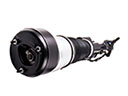 2007 Mercury Grand Marquis Air Suspension
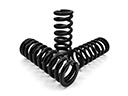 2007 Mercury Grand Marquis Coil Springs
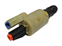 2007 Mercury Grand Marquis Air Suspension Solenoid
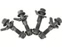 2007 Mercury Grand Marquis Alignment Bolt
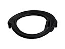 2007 Mercury Grand Marquis Coil Spring Insulator
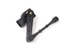 2007 Mercury Grand Marquis Ride Height Sensor
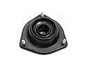 2007 Mercury Grand Marquis Shock And Strut Mount
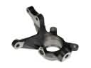 2007 Mercury Grand Marquis Steering Knuckle
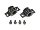 2007 Mercury Grand Marquis Sway Bar Bracket
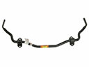 2007 Mercury Grand Marquis Sway Bar Kit
 2007 Mercury Grand Marquis Sway Bar Link
 2007 Mercury Grand Marquis Wheel Seal