FordParts
My Garage
My Account
Cart
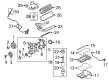
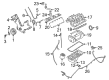
OEM 2008 Ford E-150 Intake Manifold
Engine Intake Manifold- Select Vehicle by Model
- Select Vehicle by VIN
Select Vehicle by Model
orMake
Model
Year
Select Vehicle by VIN
For the most accurate results, select vehicle by your VIN (Vehicle Identification Number).
3 Intake Manifolds found


2008 Ford E-150 Intake Manifold Part Number: AC2Z-9424-A
$317.80 MSRP: $466.67You Save: $148.87 (32%)Product Specifications- Other Name: Manifold Assembly - Inlet; Engine Intake Manifold
- Base No.: 9424
- Item Weight: 21.30 Pounds
- Item Dimensions: 22.1 x 19.4 x 12.9 inches
- Condition: New
- Fitment Type: Direct Replacement
- SKU: AC2Z-9424-A
- Warranty: This genuine part is guaranteed by Ford's factory warranty.


2008 Ford E-150 Intake Manifold Part Number: 7L3Z-9424-F
Product Specifications- Other Name: Manifold Assembly - Inlet; Engine Intake Manifold
- Replaces: 7L3Z-9424-B, 7L3Z-9424-C, 7L3Z-9424-E
- Base No.: 9424
- Item Weight: 17.70 Pounds
- Item Dimensions: 24.5 x 17.9 x 16.6 inches
- Condition: New
- Fitment Type: Direct Replacement
- SKU: 7L3Z-9424-F
- Warranty: This genuine part is guaranteed by Ford's factory warranty.

2008 Ford E-150 Intake Manifold Part Number: 9C2Z-9424-AA
Product Specifications- Other Name: Manifold Assembly - Inlet
- Base No.: 9424
- Item Weight: 13.50 Pounds
- Item Dimensions: 20.5 x 17.8 x 11.1 inches
- Condition: New
- Fitment Type: Direct Replacement
- SKU: 9C2Z-9424-AA
- Warranty: This genuine part is guaranteed by Ford's factory warranty.
2008 Ford E-150 Intake Manifold
If you're seeking quality and affordability, look no further than our extensive inventory of genuine 2008 Ford E-150 Intake Manifold available at FordPartsDeal.com. You can confidently purchase our OEM 2008 Ford E-150 Intake Manifold as they are supported by the manufacturer's warranty and our hassle-free return policy, alongside the benefit of our fast delivery service.
2008 Ford E-150 Intake Manifold Parts Q&A
- Q: How to remove the intake manifold on a 4.6L engine on 2008 Ford E-150?A: In order to clear the intake manifold of a 4.6L engine, make sure that the fuel pressure is relieved and that flames are prevented. Disassemble different parts, such as the battery, hoses and electrical connectors. Take out the manifold and replace with new gaskets, screwing bolts up one at a time. Connect all the parts and charge up the cooling system.
Related 2008 Ford E-150 Parts
 2008 Ford E-150 Air Duct
 2008 Ford E-150 Air Filter
 2008 Ford E-150 Fuel Filler Hose
 2008 Ford E-150 Fuel Filler Neck
 2008 Ford E-150 Fuel Filter
 2008 Ford E-150 Fuel Level Sensor
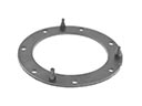 2008 Ford E-150 Fuel Pump Gasket
 2008 Ford E-150 Fuel Pump Tank Seal
 2008 Ford E-150 Fuel Tank
 2008 Ford E-150 Fuel Tank Sending Unit
 2008 Ford E-150 Fuel Tank Strap
 2008 Ford E-150 Gas Cap