My Garage
Cart

OEM 2008 Lincoln Mark LT Intake Manifold

Engine Intake Manifold
  • Select Vehicle by Model
  • Select Vehicle by VIN
Select Vehicle by Model
Make
Model
Year
or
Select Vehicle by VIN
For the most accurate results, select vehicle by your VIN (Vehicle Identification Number).

1 Intake Manifold found

  • 2008 Lincoln Mark LT Intake Manifold - 5L1Z-9424-A
    2008 Lincoln Mark LT Intake Manifold Diagram - 5L1Z-9424-A
    View related parts
    Product Specifications
    • Other Name: Manifold Assembly - Inlet; Engine Intake Manifold; Lower Manifold
    • Replaces: 5L1Z-9424-AB
    • Base No.: 9424
    • Item Weight: 22.10 Pounds
    • Item Dimensions: 23.5 x 19.4 x 15.8 inches
    • Condition: New
    • Fitment Type: Direct Replacement
    • SKU: 5L1Z-9424-A
    • Warranty: This genuine part is guaranteed by Ford's factory warranty.
    More Info
    Fits the following 2008 Lincoln Mark LT Submodels:
    • Base | 8 Cyl 5.4 L GAS

2008 Lincoln Mark LT Intake Manifold

If you're seeking quality and affordability, look no further than our extensive inventory of genuine 2008 Lincoln Mark LT Intake Manifold available at FordPartsDeal.com. You can confidently purchase our OEM 2008 Lincoln Mark LT Intake Manifold as they are supported by the manufacturer's warranty and our hassle-free return policy, alongside the benefit of our fast delivery service.

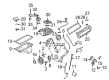
2008 Lincoln Mark LT Intake Manifold Parts Questions & Experts Answers

  • Q: How to remove and replace the intake manifold on 2008 Lincoln Mark LT?
    A: Safety must be the top priority before attempting to remove or install the intake manifold because flammable mixtures exist in fuel components. Competent managers need to lower fuel system pressure before removing the spring-lock coupling from the fuel supply tube. First drain all cooling system fluids and then remove both the generator and air cleaner before separating the upper radiator hose from its housing at the thermostat and the heater coolant hose from the bypass tube. Remove the evaporative emissions (EVAP) tube from the intake manifold through the quick connect coupling. Disconnect the electrical connector of both the fuel rail pressure and temperature sensor along with vacuum fitting and detach eight fuel injector and four LH ignition coil electrical connectors. The technical intervention requires removing electronic throttle control along with throttle position (TP) sensor as well as heated PCV element and additional connectors for engine oil pressure (EOP) sensor, LH camshaft position (CMP) sensor, LH variable camshaft timing (VCT) solenoid, and LH radio ignition interference capacitor and throttle position (TP) sensor. Place the wiring harness out of the way following the removal of the retainers affixed to the LH valve cover studs then disconnect the brake booster vacuum hose connecting to the intake manifold vacuum tube. A plastic scraping tool should be used to clean the surfaces while removing the coolant bypass tube; discard the gaskets before this procedure. Apply silicone gasket remover to cleaning surfaces while using metal surface prep to inspect them. You should first disconnect the electrical connector of the charge motion control valve (CMCV) and both the intake manifold vacuum tube and the cylinder head temperature (CHT) sensor jumper harness electrical connector. The installation process starts with knocking out the RH heated exhaust gas oxygen sensor (HO2S) electrical connector while removing the nut attached to dismantle the engine wiring harness retainer connecting to the CMCV stud followed by disconnecting the LH and RH knock sensor (KS) electrical connectors. The technician must wash and check the mating surfaces again following removal of the intake manifold as well as disposal of the current gaskets. When installing the system check that the electrical and vacuum harnesses should not hinder the operation of the CMCV control rods. Place new gaskets on the intake manifold before installation while tightening the three bolts to 10 Nm (89 lb-in). When installing the intake manifold bolts it is important to start by applying torque of 2 Nm (18 lb-in) followed by applying 10 Nm (89 lb-in). Attach the electrical connector for HO2S and then secure the retainer harness to the CMCV stud while rebuilt the CMCV connector. Connect the CHT sensor jumper harness with the LH and RH KS electrical connectors and the intake manifold vacuum tube. The brake booster vacuum hose needs reinstallation while the engine wiring harness needs placement before applying the retainers to the LH valve cover stud bolts. Connect the LH radio ignition interference capacitor alongside the LH VCT solenoid and the LH CMP sensor and EOP sensor and their corresponding four ignition coil electrical connectors. Reconnect the series of components which include the heated PCV element together with the TP sensor and eight fuel injector electrical connectors. First reconnect the fuel rail pressure and temperature sensor electrical connector along with its vacuum connector before establishing spring lock coupling on the fuel rail supply tube. After properly positioning the PCV tube with EVAP tube you should join them to other tubes including heater coolant hose and upper radiator hose. Reinstall the generator with the air cleaner before you execute a cooling system fill and bleed procedure.

Related 2008 Lincoln Mark LT Parts