FordParts
My Garage
My Account
Cart
OEM Lincoln Mark LT Intake Manifold
Engine Intake Manifold- Select Vehicle by Model
- Select Vehicle by VIN
Select Vehicle by Model
orMake
Model
Year
Select Vehicle by VIN
For the most accurate results, select vehicle by your VIN (Vehicle Identification Number).
1 Intake Manifold found


Lincoln Mark LT Intake Manifold Part Number: 5L1Z-9424-A
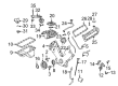
Lincoln Mark LT Intake Manifold
OEM Intake Manifold boasts unmatched quality. Each part goes through full quality checks. They adhere to Lincoln's official factory standards. These steps remove flaws and inconsistencies. So you can get Intake Manifold with long life and a perfect fit. Come to our website and find genuine Lincoln Mark LT parts. We keep a wide inventory of OEM Mark LT parts at the highly affordable prices. It's easy to search, compare, and pick what you need. You'll love the clear info and simple checkout. We offer top-rated customer service, and we reply fast. We also ship promptly to ensure your order arrives on time.
The Intake Manifold is an essential which dramatically improves the performance and the durability of the Lincoln Mark LT luxury pickup truck. Intended to feed air or air/fuel mixture to each cylinder, Intake Manifold is significant in optimising engine power on every Lincoln Mark LT model. Made from newer plastic material for the later generations this Intake Manifold not only takes advantage of lighter weight but also has better heat dissipation properties, meaning cooler air enters the combustion chamber for the ultimate in efficiency. The Intake Manifold comes with the flexibility of compatibility with multiport fuel injection and the Gasoline Direct Injection (GDI). The above evolution in manifold technology shows Lincoln's effort to improve efficiency and safety of the engines that powers the Mark LT and therefore make the automobile unique in the market. Other usable features including "the ability to manage air delivery effectively" also sets Unique Intake Manifold out of competition. Due to its renown for production of reliable and performance intensive products, the Intake Manifold is a must have for any driver who wants to get the optimal out of his car. In sum, the Intake Manifold contributes not just to the vehicles' performance upgrade but also adds up to Lincoln mystique and tradition of elegance in automobile manufacturing.
Lincoln Mark LT Intake Manifold Parts and Q&A
- Q: How to remove and replace the intake manifold on Lincoln Mark LT?A:Safety must be the top priority before attempting to remove or install the intake manifold because flammable mixtures exist in fuel components. Competent managers need to lower fuel system pressure before removing the spring-lock coupling from the fuel supply tube. First drain all cooling system fluids and then remove both the generator and air cleaner before separating the upper radiator hose from its housing at the thermostat and the heater coolant hose from the bypass tube. Remove the evaporative emissions (EVAP) tube from the intake manifold through the quick connect coupling. Disconnect the electrical connector of both the fuel rail pressure and temperature sensor along with vacuum fitting and detach eight Fuel Injector and four LH Ignition Coil electrical connectors. The technical intervention requires removing electronic throttle control along with throttle position (TP) sensor as well as heated PCV element and additional connectors for engine oil pressure (EOP) sensor, LH camshaft position (CMP) sensor, LH variable camshaft timing (VCT) solenoid, and LH radio ignition interference capacitor and throttle position (TP) sensor. Place the wiring harness out of the way following the removal of the retainers affixed to the LH valve cover studs then disconnect the brake booster vacuum hose connecting to the intake manifold vacuum tube. A plastic scraping tool should be used to clean the surfaces while removing the coolant bypass tube; discard the gaskets before this procedure. Apply silicone gasket remover to cleaning surfaces while using metal surface prep to inspect them. You should first disconnect the electrical connector of the charge motion control valve (CMCV) and both the intake manifold vacuum tube and the cylinder head temperature (CHT) sensor jumper harness electrical connector. The installation process starts with knocking out the RH heated exhaust gas oxygen sensor (HO2S) electrical connector while removing the nut attached to dismantle the engine wiring harness retainer connecting to the CMCV stud followed by disconnecting the LH and RH Knock Sensor (KS) electrical connectors. The technician must wash and check the mating surfaces again following removal of the intake manifold as well as disposal of the current gaskets. When installing the system check that the electrical and vacuum harnesses should not hinder the operation of the CMCV control rods. Place new gaskets on the intake manifold before installation while tightening the three bolts to 10 Nm (89 lb-in). When installing the intake manifold bolts it is important to start by applying torque of 2 Nm (18 lb-in) followed by applying 10 Nm (89 lb-in). Attach the electrical connector for HO2S and then secure the retainer harness to the CMCV stud while rebuilt the CMCV connector. Connect the CHT sensor jumper harness with the LH and RH KS electrical connectors and the intake manifold vacuum tube. The brake booster vacuum hose needs reinstallation while the engine wiring harness needs placement before applying the retainers to the LH valve cover stud bolts. Connect the LH radio ignition interference capacitor alongside the LH VCT solenoid and the LH CMP sensor and EOP sensor and their corresponding four ignition coil electrical connectors. Reconnect the series of components which include the heated PCV element together with the TP sensor and eight fuel injector electrical connectors. First reconnect the fuel rail pressure and temperature sensor electrical connector along with its vacuum connector before establishing spring lock coupling on the fuel rail supply tube. After properly positioning the PCV tube with EVAP tube you should join them to other tubes including heater coolant hose and upper radiator hose. Reinstall the generator with the air cleaner before you execute a cooling system fill and bleed procedure.

Related Lincoln Mark LT Parts
 Lincoln Mark LT Air Filter
 Lincoln Mark LT Air Filter Box
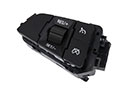 Lincoln Mark LT Cruise Control Switch
 Lincoln Mark LT Fuel Filter
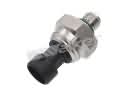 Lincoln Mark LT Fuel Pressure Sensor
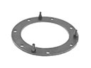 Lincoln Mark LT Fuel Pump Gasket
 Lincoln Mark LT Fuel Pump Seal
 Lincoln Mark LT Fuel Sending Unit
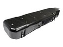 Lincoln Mark LT Fuel Tank Skid Plate
 Lincoln Mark LT Fuel Tank Strap
 Lincoln Mark LT Intake Manifold Gasket
 Lincoln Mark LT Throttle Body Gasket