FordParts
My Garage
My Account
Cart
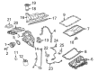
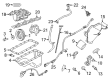
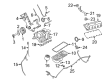
OEM 2009 Ford F-150 Intake Manifold
Engine Intake Manifold- Select Vehicle by Model
- Select Vehicle by VIN
Select Vehicle by Model
orMake
Model
Year
Select Vehicle by VIN
For the most accurate results, select vehicle by your VIN (Vehicle Identification Number).
4 Intake Manifolds found


2009 Ford F-150 Intake Manifold Part Number: 9L3Z-9424-F
$561.38 MSRP: $831.67You Save: $270.29 (33%)Ships in 1-3 Business DaysProduct Specifications- Other Name: Manifold Assembly - Inlet; Engine Intake Manifold
- Manufacturer Note: For CMVC Retaining Clips, Use W710420-S437 (4 Per Package)
- Replaces: 9L3Z-9424-B
- Base No.: 9424
- Item Weight: 23.10 Pounds
- Item Dimensions: 25.2 x 18.2 x 19.1 inches
- Condition: New
- Fitment Type: Direct Replacement
- SKU: 9L3Z-9424-F
- Warranty: This genuine part is guaranteed by Ford's factory warranty.


2009 Ford F-150 Intake Manifold Part Number: 9L3Z-9424-H
$301.91 MSRP: $443.33You Save: $141.42 (32%)Product Specifications- Other Name: Manifold Assembly - Inlet; Engine Intake Manifold
- Replaces: 9L3Z-9424-A
- Base No.: 9424
- Item Weight: 21.50 Pounds
- Item Dimensions: 20.7 x 20.3 x 15.9 inches
- Condition: New
- Fitment Type: Direct Replacement
- SKU: 9L3Z-9424-H
- Warranty: This genuine part is guaranteed by Ford's factory warranty.


2009 Ford F-150 Intake Manifold Part Number: 9L3Z-9424-E
$469.89 MSRP: $690.00You Save: $220.11 (32%)Product Specifications- Other Name: Manifold Assembly - Inlet; Engine Intake Manifold
- Manufacturer Note: Less Electric Heated PCV
- Replaced by: PU7Z-9424-B
- Base No.: 9424
- Item Weight: 24.10 Pounds
- Item Dimensions: 24.7 x 17.9 x 16.6 inches
- Condition: New
- Fitment Type: Direct Replacement
- SKU: 9L3Z-9424-E
- Warranty: This genuine part is guaranteed by Ford's factory warranty.

2009 Ford F-150 Intake Manifold Part Number: 9L3Z-9424-D
Product Specifications- Other Name: Manifold Assembly - Inlet; Engine Intake Manifold
- Manufacturer Note: With Electric Heated PCV
- Base No.: 9424
- Item Weight: 16.70 Pounds
- Item Dimensions: 22.4 x 17.3 x 15.6 inches
- Condition: New
- Fitment Type: Direct Replacement
- SKU: 9L3Z-9424-D
- Warranty: This genuine part is guaranteed by Ford's factory warranty.
2009 Ford F-150 Intake Manifold
If you're seeking quality and affordability, look no further than our extensive inventory of genuine 2009 Ford F-150 Intake Manifold available at FordPartsDeal.com. You can confidently purchase our OEM 2009 Ford F-150 Intake Manifold as they are supported by the manufacturer's warranty and our hassle-free return policy, alongside the benefit of our fast delivery service.
2009 Ford F-150 Intake Manifold Parts Q&A
- Q: How to service and repair the intake manifold on 2009 Ford F-150?A: The repair work on an intake manifold requires first ensuring total safety through the elimination of open flames near fuel-related components because highly dangerous fuel mixtures exist. The starting process begins with disconnecting the battery ground cable followed by taking out the Air Cleaner outlet pipe and draining the cooling system fluid. The service procedure starts with removing the fuel rail along with injectors followed by quick connect coupling detachment and PCV tube removal. Then disconnect the heated PCV element electric connector as well as the brake booster vacuum hose from the check valve. The accessory drive belt tensioner receives clockwise rotation for pulley generator belt release while you detach the radio interference capacitor harness from its generator wiring position. Two generator bracket-to-coolant crossover bolts should be removed before the two generator nuts receive a slight loosening and generator bracket and wiring harness collection for separate placement. Start by detaching ten intake manifold bolts before releasing clamps that disconnect the upper radiator hose from the thermostat housing and the heater hose from the coolant crossover manifold. Cut out two bolts from the coolant crossover manifold and dispose of its two gaskets. Take the intake manifold forward while removing the three wiring harness retainers from its back section then disconnect the electrical connector for the Charge Motion Control Valve (CMCV). A plastic scraping tool should be used for cleaning both the intake manifold as well as the coolant crossover manifold mounting surfaces before discarding the installed gaskets. The installation process must include an examination of the intake manifold for metal particles if the engine underwent repairs or engine replacement because of upper engine failure and the presence of such debris requires a fresh intake manifold. The CMCV electrical connector should be connected after positioning the intake manifold with two new gaskets installed. Install the wiring harness retainers at the rear part of intake manifold while fitting the brake booster vacuum hose through the wiring harness retainer. install two new gaskets underneath the coolant crossover manifold before positioning the assembly according to specifications while securing the two bolts to 10 Nm (89 lb-in). Secure the hose clamp onto every heater hose and upper radiator hose in their proper locations. Use two steps to tighten the ten intake manifold bolts starting at 2 Nm (18 lb-in) then continuing to 10 Nm (89 lb-in). Secure the generator through two mounting nuts that should be tightened to 25 Nm (18 lb-ft). Afterward, install and tighten the two generator bracket-to-coolant crossover bolts to 10 Nm (89 lb-in). The driving procedure includes reattaching the generator wiring harness retainer for radio interference capacitors while tensioning the accessory drive belt clockwise on the generator pulley using the accessory drive belt tensioner and reconnecting the brake booster check valve hose. Close the circuit for the heated PCV element electrical connector after installing the PCV tube, replacing the fuel rail and ACL outlet pipe and reconnecting the battery ground cable together with filling the cooling system.
Related 2009 Ford F-150 Parts
 2009 Ford F-150 Mass Air Flow Sensor
 2009 Ford F-150 Air Duct
 2009 Ford F-150 Air Filter Box
 2009 Ford F-150 Fuel Filler Neck
 2009 Ford F-150 Fuel Pump Gasket
 2009 Ford F-150 Fuel Pump Tank Seal
 2009 Ford F-150 Fuel Tank
 2009 Ford F-150 Fuel Tank Lock Ring
 2009 Ford F-150 Fuel Tank Skid Plate
 2009 Ford F-150 Fuel Tank Strap
 2009 Ford F-150 Intake Manifold Gasket
 2009 Ford F-150 Throttle Body