FordParts
My Garage
My Account
Cart
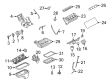
OEM 2009 Ford Mustang Intake Manifold
Engine Intake Manifold- Select Vehicle by Model
- Select Vehicle by VIN
Select Vehicle by Model
orMake
Model
Year
Select Vehicle by VIN
For the most accurate results, select vehicle by your VIN (Vehicle Identification Number).
4 Intake Manifolds found

2009 Ford Mustang Intake Manifold, Lower Part Number: 7R3Z-9424-AA
$259.92 MSRP: $381.67You Save: $121.75 (32%)Ships in 1-2 Business DaysProduct Specifications- Other Name: Manifold Assembly - Inlet; Engine Intake Manifold, Lower
- Position: Lower
- Base No.: 9424B
- Item Weight: 6.50 Pounds
- Item Dimensions: 20.8 x 10.2 x 4.2 inches
- Condition: New
- Fitment Type: Direct Replacement
- SKU: 7R3Z-9424-AA
- Warranty: This genuine part is guaranteed by Ford's factory warranty.


2009 Ford Mustang Intake Manifold Part Number: AR3Z-9424-C
$430.17 MSRP: $631.67You Save: $201.50 (32%)Product Specifications- Other Name: Manifold Assembly - Inlet; Engine Intake Manifold
- Replaces: AR3Z-9424-B, AR3Z-9424-A, 4R3Z-9424-EL, 7R3Z-9424-BA
- Item Weight: 21.60 Pounds
- Item Dimensions: 24.2 x 18.9 x 16.2 inches
- Condition: New
- Fitment Type: Direct Replacement
- SKU: AR3Z-9424-C
- Warranty: This genuine part is guaranteed by Ford's factory warranty.


2009 Ford Mustang Intake Manifold Part Number: 5R3Z-9424-BA
Product Specifications- Other Name: Manifold Assembly - Inlet; Engine Intake Manifold
- Base No.: 9424
- Item Weight: 11.80 Pounds
- Item Dimensions: 14.0 x 16.9 x 27.2 inches
- Condition: New
- Fitment Type: Direct Replacement
- SKU: 5R3Z-9424-BA
- Warranty: This genuine part is guaranteed by Ford's factory warranty.

2009 Ford Mustang Intake Manifold, Upper Part Number: 7R3Z-9424-CA
$618.75 MSRP: $916.67You Save: $297.92 (33%)Product Specifications- Other Name: Manifold Assembly - Inlet; Engine Intake Manifold, Upper
- Position: Upper
- Base No.: 9424A
- Item Weight: 22.00 Pounds
- Item Dimensions: 16.6 x 17.1 x 14.6 inches
- Condition: New
- Fitment Type: Direct Replacement
- SKU: 7R3Z-9424-CA
- Warranty: This genuine part is guaranteed by Ford's factory warranty.
2009 Ford Mustang Intake Manifold
If you're seeking quality and affordability, look no further than our extensive inventory of genuine 2009 Ford Mustang Intake Manifold available at FordPartsDeal.com. You can confidently purchase our OEM 2009 Ford Mustang Intake Manifold as they are supported by the manufacturer's warranty and our hassle-free return policy, alongside the benefit of our fast delivery service.
2009 Ford Mustang Intake Manifold Parts Q&A
- Q: How to service and repair the intake manifold on 2009 Ford Mustang?A: Cleanliness must be established before servicing or repairing the intake manifold in order to avoid preventing engine failure from foreign materials. Detach the Air Cleaner outlet pipe then disconnect the radio capacitor electrical connector and remove the RH spark plug wires from the ignition coil followed by the RH spark plug wire retainer from the intake manifold. Detach the two upper and two lower bolts which secure the ignition coil bracket and set the combination of ignition coil and bracket assembly to one side. When performing the diagnosis disconnect the EGR system module electrical connector alongside its tube as well as the brake booster vacuum hose and the vacuum tube from the fuel rail pressure and temperature sensor together with the vapor tube from the intake manifold and the PCV tube. Remove the intake manifold by first disconnecting the Throttle Position (TP) sensor and Throttle Body (TB) electrical connectors then the Knock Sensor (KS) electrical connector retainer before unscrewing its eight bolts. Check for metal damage when installing the intake manifold since engines experiencing upper engine failure need replacement or repair. Install a new manifold when metal contamination is observed in such cases. The mechanic should clean all surfaces that require sealing then proceed to install new gaskets when needed. Attach the intake manifold to its position while installing its eight bolts to a torque of 10 Nm (89 lb-in) in a specific tightening order. The first step is to attach the PCV tube followed by installation of the KS electrical connector retainer. Reconnect the TP sensor and TB electrical connectors while completing the work. Connect the vapor tube together with the vacuum tube to fuel rail pressure and temperature sensor and install the brake booster vacuum hose to the intake manifold. Start by connecting the EGR system module tube first then secure it with 40 Nm (30 lb-ft) torque and proceed to connect the EGR system module electrical connector. Place the ignition coil bracket assembly in its proper position then secure both lower bolts with the M8 bolt at 24 Nm (18 lb-ft) and M12 bolt at 34 Nm (25 lb-ft). The procedure ends by attaching the RH spark plug wire retainer and reconnecting RH spark plug wires to the ignition coil along with reconnecting the radio capacitor electrical connector. Finish the operation by reinstalling the ACL outlet pipe.
Related 2009 Ford Mustang Parts
 2009 Ford Mustang Fuel Tank
 2009 Ford Mustang Air Filter
 2009 Ford Mustang Fuel Filter
 2009 Ford Mustang Mass Air Flow Sensor
 2009 Ford Mustang Air Duct
 2009 Ford Mustang Air Filter Box
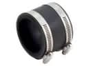 2009 Ford Mustang Air Intake Coupling
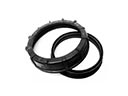 2009 Ford Mustang Fuel Pump Seal
 2009 Ford Mustang Fuel Pump Tank Seal
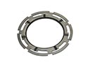 2009 Ford Mustang Fuel Tank Lock Ring
 2009 Ford Mustang Fuel Tank Sending Unit
 2009 Ford Mustang Fuel Tank Strap