FordParts
My Garage
My Account
Cart
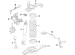
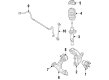
OEM 2009 Lincoln MKS Shock Absorber
Suspension Shock Absorber- Select Vehicle by Model
- Select Vehicle by VIN
Select Vehicle by Model
orMake
Model
Year
Select Vehicle by VIN
For the most accurate results, select vehicle by your VIN (Vehicle Identification Number).
5 Shock Absorbers found


2009 Lincoln MKS Shock Absorber Part Number: CA5Z-18125-B
$119.34 MSRP: $196.36You Save: $77.02 (40%)Ships in 1-2 Business DaysProduct Specifications- Other Name: Shock Absorber Assembly; Suspension Strut and Shock Kit; Shock Absorber Set; Strut Shock Kit; Shock
- Manufacturer Note: RH/LH
- Replaces: 8A5Z-18125-A, AST-379, AA5Z-18125-B, ASH-12269, AA5Z-18125-A, AST-378, AST-469, 8A5Z-18125-G, AA5Z-18125-C, 8A5Z-18125-B, AST-882, ASH-1254, BA5Z-18125-A, ASH-1242, CA5Z-18125-A, ASH-1252, CA5Z-18125-C, AST-468
- Base No.: 18125
- Item Weight: 7.30 Pounds
- Item Dimensions: 3.3 x 3.4 x 26.5 inches
- Condition: New
- Fitment Type: Direct Replacement
- Require Quantity: 2
- SKU: CA5Z-18125-B
- Warranty: This genuine part is guaranteed by Ford's factory warranty.


2009 Lincoln MKS Strut, Front Driver Side Part Number: 8A5Z-18124-H
$164.65 MSRP: $270.91You Save: $106.26 (40%)Ships in 1-2 Business DaysProduct Specifications- Other Name: Shock Absorber Assembly - Front; Suspension Strut and Shock Kit; Shock Absorber Set.; Shock Absorber
- Position: Front Driver Side
- Base No.: 18124
- Item Weight: 13.70 Pounds
- Item Dimensions: 8.2 x 8.0 x 25.0 inches
- Condition: New
- Fitment Type: Direct Replacement
- SKU: 8A5Z-18124-H
- Warranty: This genuine part is guaranteed by Ford's factory warranty.
2009 Lincoln MKS Strut, Front Driver Side Part Number: 8A5Z-18124-F
$157.11 MSRP: $270.91You Save: $113.80 (43%)Ships in 1-2 Business DaysProduct Specifications- Other Name: Shock Absorber Assembly - Front; Suspension Strut and Shock Kit; Shock Absorber Set.; Shock Absorber
- Position: Front Driver Side
- Replaced by: 8A5Z-18124-H
- Base No.: 18124
- Item Weight: 13.10 Pounds
- Item Dimensions: 9.8 x 8.8 x 26.1 inches
- Condition: New
- Fitment Type: Direct Replacement
- SKU: 8A5Z-18124-F
- Warranty: This genuine part is guaranteed by Ford's factory warranty.

2009 Lincoln MKS Strut, Passenger Side Part Number: AA5Z-18124-C
Product Specifications- Other Name: Shock Absorber Assembly; Suspension Strut and Shock Kit; Shock Absorber Set; Strut Shock Kit; Shock Absorber
- Position: Passenger Side
- Replaces: AA5Z-18124-E, BA5Z-18124-H, AST-1260, AST-456
- Base No.: 18124
- Item Weight: 14.30 Pounds
- Item Dimensions: 10.1 x 8.9 x 25.6 inches
- Condition: New
- Fitment Type: Direct Replacement
- SKU: AA5Z-18124-C
- Warranty: This genuine part is guaranteed by Ford's factory warranty.
2009 Lincoln MKS Strut, Passenger Side Part Number: 8A5Z-18124-G
Product Specifications- Other Name: Shock Absorber Assembly; Suspension Strut and Shock Kit; Shock Absorber Set; Strut Shock Kit; Shock Absorber
- Position: Passenger Side
- Base No.: 18124
- Item Weight: 10.40 Pounds
- Item Dimensions: 9.9 x 8.6 x 26.1 inches
- Condition: New
- Fitment Type: Direct Replacement
- SKU: 8A5Z-18124-G
- Warranty: This genuine part is guaranteed by Ford's factory warranty.
2009 Lincoln MKS Shock Absorber
If you're seeking quality and affordability, look no further than our extensive inventory of genuine 2009 Lincoln MKS Shock Absorber available at FordPartsDeal.com. You can confidently purchase our OEM 2009 Lincoln MKS Shock Absorber as they are supported by the manufacturer's warranty and our hassle-free return policy, alongside the benefit of our fast delivery service.
2009 Lincoln MKS Shock Absorber Parts Q&A
- Q: How to Remove and Replace the Front Shock Absorber and Spring Assembly on 2009 Lincoln MKS?A: To change a front strut and spring assembly, unlock the steering wheel, loosen up nuts on top strut mounts and take the wheel off. Unattach the components such as the brake disc and tie rod and then take off the strut assembly. Install the new assembly, correctly torque all the nuts and parts and reattach the wheel.
Related 2009 Lincoln MKS Parts
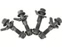 2009 Lincoln MKS Alignment Bolt
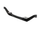 2009 Lincoln MKS Axle Beam
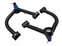 2009 Lincoln MKS Control Arm
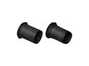 2009 Lincoln MKS Control Arm Bushing
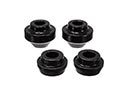 2009 Lincoln MKS Radius Arm Bushing
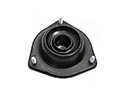 2009 Lincoln MKS Shock And Strut Mount
 2009 Lincoln MKS Steering Knuckle
 2009 Lincoln MKS Sway Bar Kit
 2009 Lincoln MKS Sway Bar Link
 2009 Lincoln MKS Track Bar
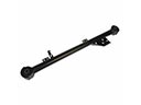 2009 Lincoln MKS Trailing Arm
 2009 Lincoln MKS Trailing Arm Bushing