FordParts
My Garage
My Account
Cart
OEM 2009 Lincoln MKX Timing Cover
Engine Timing Cover- Select Vehicle by Model
- Select Vehicle by VIN
Select Vehicle by Model
orMake
Model
Year
Select Vehicle by VIN
For the most accurate results, select vehicle by your VIN (Vehicle Identification Number).
1 Timing Cover found


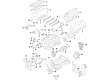
2009 Lincoln MKX Timing Cover, Front Part Number: 7T4Z-6019-C
$127.10 MSRP: $185.00You Save: $57.90 (32%)Ships in 1-3 Business DaysProduct Specifications- Other Name: Cover - Cylinder Front; Engine Timing Cover; Front Cover
- Manufacturer Note: Use RTV Silicone Sealer In Place Of Gasket For This Application. Refer To Workshop Manual For Specification
- Position: Front
- Replaces: 7T4Z-6019-GD
- Base No.: 6019
- Item Weight: 1.00 Pounds
- Item Dimensions: 6.4 x 6.2 x 6.3 inches
- Condition: New
- Fitment Type: Direct Replacement
- SKU: 7T4Z-6019-C
- Warranty: This genuine part is guaranteed by Ford's factory warranty.
2009 Lincoln MKX Timing Cover
If you're seeking quality and affordability, look no further than our extensive inventory of genuine 2009 Lincoln MKX Timing Cover available at FordPartsDeal.com. You can confidently purchase our OEM 2009 Lincoln MKX Timing Cover as they are supported by the manufacturer's warranty and our hassle-free return policy, alongside the benefit of our fast delivery service.
2009 Lincoln MKX Timing Cover Parts Q&A
- Q: How to service and repair the timing cover on 2009 Lincoln MKX?A: The starting point for all timing cover servicing and repair practices includes complete cleanliness to avoid contaminants which could cause a breakdown. The recovery of A/C system must begin after hoisting the vehicle to neutral position and installing it on the lift. First disconnect the ground cable of the battery before removing the accessory drive belt with its tensioner and power steering belt. An appropriate strap wrench should be used to unscrew the crankshaft bolt while removing its washer for disposal. A 3 jaw puller will extract the crankshaft pulley while the oil seal remover functions to remove the crankshaft front seal. Unfasten the exhaust flexible pipe clamp before you detach two exhaust hangers and extract the four nuts with the exhaust flexible pipe and Y-pipe assembly while discarding the nuts and gasket. The technician should first remove two nuts alongside the roll restrictor heat shield before moving on to the roll restrictor through bolt and heat shield then finishing with the removal of the two roll restrictor-to-transaxle bracket plate bolts. First cut the roll restrictor-to-subframe through bolt loose while moving the roll restrictor with transaxle bracket plate to the side. Strip away the right-hand front halfshaft after uncoupling the transaxle bracket and its three securing bolts. Drain the engine oil through the drain plug before reinstalling it with a torque of 27 Nm (20 lb-ft). Detach the engine-block-heater harness from the radiator support and A/C suction tube and engine wiring harness only when equipped. Start by taking off the engine air cleaner combined with the ACL outlet pipe and then detach both left-hand and right-hand valve covers. Separate the safety clip from the A/C suction tube fitting before disconnecting it and placing the tube to the side. Detach the bolt securing the A/C pressure tube bracket before disconnecting the fitting of the tube while discarding the O-ring and setting the tube to the side. The procedure starts with disconnecting the two engine wiring harness connectors and removing the bolt and ground wire attached to the engine front cover. Next, separate the nut and ground wire connected to the engine front cover stud and the cowl stud while removing the radio interference capacitor wire from both points. First disconnect the electrical connectors of the purge valve and the PCM along with three other connectors before setting the wiring harness to the side. The technician should remove three bolts before positioning the degas bottle out of the way. Free access should be maintained between engine front components and vehicle structure to enable trouble-free engine front cover insertion. The power steering reservoir needs its nuts removed so mechanic's wire can secure both tank and hose afterward they are moved away from engine front space. The pump and hose require support after removing their three bolts. Take out all bolts which secure the left-hand and right-hand variable camshaft timing solenoids. Place a floor jack and oil pan holding fixture under the oil pan with detailed alignment to avoid any possible damage. A careful engine procedure begins with opening the transaxle mount through bolt to lower the engine front and prevent hydraulic transaxle mount internal damage. Begin by removing the engine mount brace bolt followed by its nut and engine mount brace before uninstalling the four nuts securing the engine mount and three bolts together with the engine mount. Two bolts need to be detached from the engine mount bracket before hand tools can remove both engine mount studs and two upper engine mount bracket bolts. You must lower the engine to get to the lower engine mount bracket bolt which you must loosen before removing it together with the bracket bolt. To separate the engine front cover from the cylinder block simply install six front cover bolts into its threaded holes while pressing each screw by hand and afterward tighten them in a criss-cross method to break loose the seal before pulling off the front cover.
Related 2009 Lincoln MKX Parts
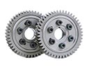 2009 Lincoln MKX Cam Gear
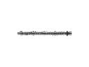 2009 Lincoln MKX Camshaft
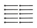 2009 Lincoln MKX Cylinder Head Bolts
 2009 Lincoln MKX Dipstick
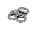 2009 Lincoln MKX Drain Plug Washer
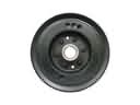 2009 Lincoln MKX Harmonic Balancer
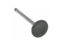 2009 Lincoln MKX Intake Valve
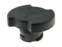 2009 Lincoln MKX Oil Filler Cap
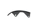 2009 Lincoln MKX Timing Chain Guide
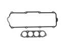 2009 Lincoln MKX Valve Cover Gasket
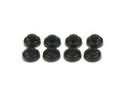 2009 Lincoln MKX Valve Stem Seal
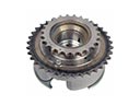 2009 Lincoln MKX Variable Timing Sprocket