FordParts
My Garage
My Account
Cart
OEM 2009 Lincoln Town Car Intake Manifold
Engine Intake Manifold- Select Vehicle by Model
- Select Vehicle by VIN
Select Vehicle by Model
orMake
Model
Year
Select Vehicle by VIN
For the most accurate results, select vehicle by your VIN (Vehicle Identification Number).
1 Intake Manifold found


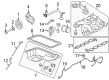
2009 Lincoln Town Car Intake Manifold Part Number: 9W7Z-9424-A
$334.83 MSRP: $491.67You Save: $156.84 (32%)Product Specifications- Other Name: Manifold Assembly - Inlet; Engine Intake Manifold
- Replaced by: PU7Z-9424-A
- Base No.: 9424
- Item Weight: 18.90 Pounds
- Item Dimensions: 22.4 x 19.4 x 14.4 inches
- Condition: New
- Fitment Type: Direct Replacement
- SKU: 9W7Z-9424-A
- Warranty: This genuine part is guaranteed by Ford's factory warranty.
2009 Lincoln Town Car Intake Manifold
If you're seeking quality and affordability, look no further than our extensive inventory of genuine 2009 Lincoln Town Car Intake Manifold available at FordPartsDeal.com. You can confidently purchase our OEM 2009 Lincoln Town Car Intake Manifold as they are supported by the manufacturer's warranty and our hassle-free return policy, alongside the benefit of our fast delivery service.
2009 Lincoln Town Car Intake Manifold Parts Q&A
- Q: How to service the intake manifold on 2009 Lincoln Town Car?A: To replace intake manifold service, place the vehicle on a hoist, loosen required parts, and take out the intake manifold. Wipe the sealing surfaces, lay new gaskets, and reassemble in reverse order, be sure that all connections and bolts are firmly tightened to given torque requirements. Lastly, fill and bleed engine cooling system.
Related 2009 Lincoln Town Car Parts
 2009 Lincoln Town Car Fuel Pump
 2009 Lincoln Town Car Air Filter
 2009 Lincoln Town Car Fuel Filter
 2009 Lincoln Town Car Fuel Tank
 2009 Lincoln Town Car Air Duct
 2009 Lincoln Town Car Air Filter Box
 2009 Lincoln Town Car Fuel Filler Neck
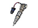 2009 Lincoln Town Car Fuel Injector
 2009 Lincoln Town Car Fuel Pump Tank Seal
 2009 Lincoln Town Car Gas Cap
 2009 Lincoln Town Car Intake Manifold Gasket
 2009 Lincoln Town Car Throttle Body