FordParts
My Garage
My Account
Cart
OEM 2009 Lincoln Town Car Universal Joint
U-Joint- Select Vehicle by Model
- Select Vehicle by VIN
Select Vehicle by Model
orMake
Model
Year
Select Vehicle by VIN
For the most accurate results, select vehicle by your VIN (Vehicle Identification Number).
1 Universal Joint found


2009 Lincoln Town Car Universal Joints, Rear Part Number: 7L1Z-4635-B
$40.51 MSRP: $60.67You Save: $20.16 (34%)Product Specifications- Other Name: Kit - Universal Joint Repair; Front Center, Rear, CV Joint; U Joint; U-Joint
- Manufacturer Note: 1350
- Position: Rear
- Replaces: F5TZ-4635-A, 4L3Z-4841-FB, 7L1Z-4635-A
- Condition: New
- Fitment Type: Direct Replacement
- SKU: 7L1Z-4635-B
- Warranty: This genuine part is guaranteed by Ford's factory warranty.
2009 Lincoln Town Car Universal Joint
If you're seeking quality and affordability, look no further than our extensive inventory of genuine 2009 Lincoln Town Car Universal Joint available at FordPartsDeal.com. You can confidently purchase our OEM 2009 Lincoln Town Car Universal Joint as they are supported by the manufacturer's warranty and our hassle-free return policy, alongside the benefit of our fast delivery service.
2009 Lincoln Town Car Universal Joint Parts Q&A
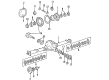
- Q: How to service and repair the driveshaft universal joint on 2009 Lincoln Town Car?A: In order to maintain the driveshaft universal joint, lay it on a work bench and label the position of different components to be assembled during re-assembly. Removal of snap rings and bearing cups is done using a C-Frame. Clean and wipe the yoke area and place new parts in, making sure that they are in place. U-joint check movement.
Related 2009 Lincoln Town Car Parts
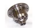 2009 Lincoln Town Car Differential
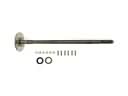 2009 Lincoln Town Car Axle Shaft
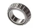 2009 Lincoln Town Car Differential Bearing
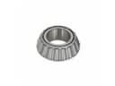 2009 Lincoln Town Car Differential Pinion Bearing
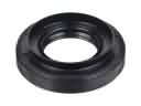 2009 Lincoln Town Car Differential Seal
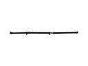 2009 Lincoln Town Car Drive Shaft
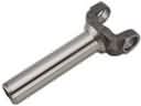 2009 Lincoln Town Car Driveshaft Yokes
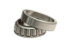 2009 Lincoln Town Car Pinion Bearing
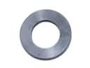 2009 Lincoln Town Car Pinion Washer
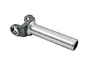 2009 Lincoln Town Car Slip Yoke
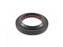 2009 Lincoln Town Car Wheel Seal