My Garage
Cart
Make sure this part fits

Ford 7L1Z-4635-B
Universal Joints, Rear

1997-2023 Ford 7L1Z4635B

Customer Questions & Expert Answers (17)
Ford 7L1Z-4635-B Universal Joints, Rear
  • Part Description
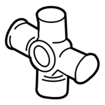
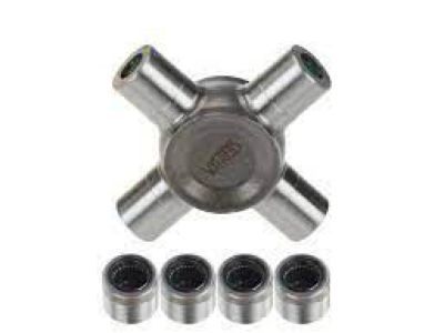
    Kit - Universal Joint Repair; Front Center, Rear, CV Joint; U Joint
  • Position
    Rear
  • Replaces
    F5TZ-4635-A, 4L3Z-4841-FB, 7L1Z-4635-A
  • Manufacturer
    Ford
Make sure this part fits
$38.33 MSRP: $54.83
You Save: $16.50 (31%)
1
ADD TO CART
  • Related Parts
  • Product Specifications
  • Vehicle Fitment
  • Customer Questions & Expert Answers
  • Product Specifications

    BrandGenuine Ford
    Manufacturer Part Number7L1Z-4635-B
    Part DescriptionKit - Universal Joint Repair; Front Center, Rear, CV Joint; U Joint
    Other NamesU-Joint
    Manufacturer Note1350
    PositionRear
    ConditionNew
    Fitment TypeDirect Replacement
    ReplacesF5TZ-4635-A, 4L3Z-4841-FB, 7L1Z-4635-A
    ManufacturerFord
    SKU7L1Z-4635-B
    WarrantyThis genuine Ford part is guaranteed by Ford's factory warranty.
    Shipping & ReturnShipping Policy Return Policy
    Warning: California's Proposition 65
  • Vehicle Fitment

    Year Make Model Trim Engine
    2007-2011 Ford Crown VictoriaBase, Fleet, LWB, LX, Police Interceptor8 Cyl 4.6 L FLEX, 8 Cyl 4.6 L GAS
    2003-2014 Ford E-150Base, Chateau, XL, XLT6 Cyl 4.2 L GAS, 8 Cyl 4.6 L FLEX, 8 Cyl 4.6 L GAS, 8 Cyl 5.4 L CNG, 8 Cyl 5.4 L FLEX, 8 Cyl 5.4 L GAS, 8 Cyl 5.4 L LPG
    1997-2002 Ford E-150 EconolineBase, XL6 Cyl 4.2 L GAS, 8 Cyl 4.6 L GAS, 8 Cyl 5.4 L BI-FUEL, 8 Cyl 5.4 L GAS
    1997-2002 Ford E-150 Econoline Club WagonChateau, Custom, XL, XLT6 Cyl 4.2 L GAS, 8 Cyl 4.6 L GAS, 8 Cyl 5.4 L BI-FUEL, 8 Cyl 5.4 L GAS
    2003-2014 Ford E-250Base6 Cyl 4.2 L GAS, 8 Cyl 4.6 L FLEX, 8 Cyl 4.6 L GAS, 8 Cyl 5.4 L CNG, 8 Cyl 5.4 L FLEX, 8 Cyl 5.4 L GAS, 8 Cyl 5.4 L LPG
    2002, 1997-1999 Ford E-250 EconolineBase6 Cyl 4.2 L GAS, 8 Cyl 5.4 L BI-FUEL, 8 Cyl 5.4 L CNG, 8 Cyl 5.4 L GAS
    1997-1998 Ford E-350 EconolineBase, XL10 Cyl 6.8 L GAS, 8 Cyl 5.4 L BI-FUEL, 8 Cyl 5.4 L CNG, 8 Cyl 5.4 L GAS, 8 Cyl 7.3 L DIESEL
    1997-2002 Ford E-350 Econoline Club WagonChateau, Custom, XL, XL HD, XLT, XLT HD10 Cyl 6.8 L GAS, 8 Cyl 5.4 L BI-FUEL, 8 Cyl 5.4 L CNG, 8 Cyl 5.4 L GAS, 8 Cyl 7.3 L DIESEL
    1999-2014 Ford E-350 Super DutyBase, Chateau, XL, XLT10 Cyl 6.8 L GAS, 8 Cyl 5.4 L BI-FUEL, 8 Cyl 5.4 L CNG, 8 Cyl 5.4 L FLEX, 8 Cyl 5.4 L GAS, 8 Cyl 5.4 L LPG, 8 Cyl 6.0 L DIESEL, 8 Cyl 7.3 L DIESEL
    2005, 2000-2003 Ford ExcursionEddie Bauer, Limited, XLS, XLT10 Cyl 6.8 L GAS, 8 Cyl 5.4 L GAS, 8 Cyl 6.0 L DIESEL
    View More
  • Customer Questions & Expert Answers

    Q:
    Can you verify if 7L1Z-4635-B is the right one for my car? Posted by FordPartsDeal Specialist
    A:
    Select Your Vehicle model to verify if part number 7L1Z-4635-B fits your car.
    Posted by FordPartsDeal Specialist
    Q:
    How to service and repair the driveshaft universal joint on Ford Crown Victoria? Posted by Customer
    A:
    The next step before servicing the driveshaft universal joint starts with driveshaft removal without vise-clamping while setting it on a suitable workbench. Draw marks indicating how the driveshaft components should be placed in relation to the driveshaft tube for future balanced reinstallation. A C-Frame and Screw Installer/Remover tool removes snap rings before allowing bearing cups to be pressed out from the driveshaft through its necessary rotations. The use of vise grips is necessary to remove bearing cups when they resist complete press-out. Clean the yoke surfaces before proceeding to inspect all components for wear and damage when removing the driveshaft slip yoke along with centering socket yoke. Execute U-joint assembly by installing new bearing cups and spiders as complete assemblies which should be obtained from the U-joint service kits while pressing the bearing cups beneath the yoke surface. When the yellow snap rings fail to provide sufficient installation ease you can substitute them with black snap rings. Check the U-joint movement by hitting each yoke with a brass or plastic hammer during the inspection of both driveshaft sides. The bearing cups need to be placed 6.3 millimeters (0.25 inches) underneath the yoke surface when performing installations.
    Posted by FordPartsDeal Specialist
    Q:
    How to service and repair the driveshaft universal joint on Ford E-150? Posted by Customer
    A:
    The first step of universal joint driveshaft service and repair includes placing the shaft on a suitable workbench and never using a vise clamp because this can create dents or fracture which leads to operation failure. First remove and discard two snap rings before setting up the C-Frame and Screw Installer/Remover inside a vise. Pliers should be used to help with removing sticking bearing cups which fail to press out completely. After placing the slip-yoke into the C-Frame you should use the C-Frame to push out one bearing cup before rotating the driveshaft slip-yoke by 180 degrees for pushing out both bearing cups and the U-joint. The driveshaft slip-yoke needs cleaning before conducting inspections to replace it with a new yoke. Construct U-Joint Kits as whole units while avoiding use of products that belong to different kits. Place a new bearing cup into the shaft yoke with needle bearings in proper position before setting the new spider in the yoke and press the cup a short distance below the snap ring groove through C-Frame usage. The assembly process requires the yellow snap rings included in the kit and black snap rings serve as a back up alternative when needed. The procedure should be repeated for installing the new snap ring on the opposite bearing cup. Complete the inspection of the U-joint for unrestricted movements by using a brass or plastic hammer to strike the yoke if binding occurs.
    Posted by FordPartsDeal Specialist
    Q:
    How to service and repair the driveshaft universal joint with a single Cardan and flange yoke on Ford E-250? Posted by Customer
    A:
    The first step for servicing the driveshaft universal joint with a single Cardan and flange yoke starts by placing the driveshaft on a workbench with caution to avoid using a vise clamp because it can cause damage. The technician marks each component before removing the 4 snap rings. A C-Frame device together with a Screw Installer/Remover enables bearing cup extraction but pliers must be used when a bearing cup fails to completely push out. Place the flange into the C-Frame while pressing out the first bearing cup. Next rotate the flange 180 degrees to press the spider and then remove the flange respectively. Using a C-Frame and Screw Installer/Remover extract the remaining bearing cups and spider from the driveshaft yoke which you should clean afterwards. The U-Joint Kits require full assembly during installation where components should never be interchanged. Position new bearing cups correctly inside the yoke before inserting the new spider into its place. Apply the C-Frame to press each bearing cup until it reaches the snap ring groove on its side and then perform the process again for the other side. Inspect the flange and perform a necessary replacement before you begin to install new bearing cups along with the flange by starting a new bearing cup in the flange and confirming the needle bearings are present. Fit the flange to the spider followed by C-Frame operation that presses the bearing cup beneath the snap ring groove on each side. Assemble the U-joint with the supplied yellow snap rings unless you face difficulties which require black snap rings. The driveshaft should be removed from the C-Frame and there you should install the 4 new snap rings keeping the bearings free from damaging impacts. Free movement of the U-joint should be examined while a light hit from a brass or plastic hammer on the yoke is necessary if binding occurs.
    Posted by FordPartsDeal Specialist
    Q:
    How to service and repair the driveshaft universal joint on Ford Expedition? Posted by Customer
    A:
    A suitable workbench should replace vise clamping when working on the driveshaft universal joint service and repair. You should index-mark the driveshaft components against the driveshaft tube because this enables accurate balancing for reinstallation. The C-Frame and Screw Installer/Remover device needs to be placed inside a vise before removing snap rings from the U-joint. Use pliers only when required to pull out a bearing cup which resists complete press-out. A procedure to remove the driveshaft flange yoke begins with placing the driveshaft flange into the C-Frame and Screw Installer/Remover while pressing out the bearing cup to rotate the driveshaft flange yoke and then pressing on the spider to remove the remaining bearing cup. Complete U-joint service kits provide the necessary components for end assembly after the yoke area cleaning process of both driveshaft and flange yoke. The C-Frame and Screw Installer/Remover should be fixed in a vise as operators install new bearing cups then position new spiders to press the bearing cups into the yoke surface. The C-Frame driveshaft removal process ends when you install the snap ring then continue with bearing cup installation on the remaining driveshaft sections. Keep direct blows away from the bearings while a brass or plastic hammer should be used for yoke strikes when binding occurs. Verify that the U-joint moves easily as the last step of maintenance.
    Posted by FordPartsDeal Specialist
    Q:
    Are the Staked Driveshaft Universal Joints Serviced Separately Within the Warranty Period on Ford Explorer? Posted by Customer
    A:
    U-joints on the staked driveshaft cannot be serviced alone during the warranty duration. Worn-out or damaged U-joints lead to requires new driveshaft replacement. When performing high mileage U-joint repairs customers can buy service kits from Ford authorized dealers who will also provide instructions.
    Posted by FordPartsDeal Specialist
    Q:
    How to service and repair the driveshaft universal joint of the snap ring type on Ford F-150? Posted by Customer
    A:
    A proper approach for servicing or repairing driveshaft universal joints requires removing driveshafts without using a vise clamp to protect them from damage. Index marks should be applied to the driveshaft components to maintain balance in the future assembly process. A C-Frame and Screw Remover/Installer removes the bearing cups and slip yoke from the driveshaft by using press action while getting rid of all snap rings. The removal task can be helped by pliers when bearing cups prove difficult to displace. Examine the bearing cup holes along with retaining ring slots for any surface defects and rust presence while verifying their clean and smooth state. The assembly process requires the use of complete U-Joint Kits which should never contain mixed components. Apply grease to all bearing cup bores before you set a new spider and cups inside a U-joint. Use a new driveshaft yoke bearing cup while checking the needle bearings are correctly positioned before pressing it until it reaches the snap ring groove. The installation requires a new yellow snap ring which must not have yellow or black snap rings on different sides. Perform this installation sequence also on the yoke side facing away from the driver. Place the slip yoke on the driveshaft while matching the index marks then reapply the bearing cup installation protocol together with the snap rings. Cup seating occurs when using a brass or plastic hammer for a forceful tap. The driveshaft needs to have U-joints that move without restriction before installing the driveshaft back into place.
    Posted by FordPartsDeal Specialist
    Q:
    How to service and repair the driveshaft universal joint on Ford F-250 Super Duty? Posted by Customer
    A:
    Service and repair of driveshaft universal joints should begin using a suitable workbench where you place the driveshaft without using a vise clamp. The double cardan yokes require index marking before discarding all snap rings. Set a swivel base vise to hold the C-Frame and Screw Installer/Remover but avoid excessive tightening which can damage the center bearing shield. Press the two bearing cups out from one side of the driveshaft center yoke using the C-Frame and Screw Installer/Remover while alternating the pressure between U-joints. A half moon punch should be inserted on the exposed spider leg while sliding the U-joint spider toward the screw side to press out the remaining bearing cups. Discard the driveshaft when the centering ball on its end yoke shows damage during the removal of bearing cups using gripping pliers. To build the assembly the spider needs to be placed in the driveshaft end yoke then a bearing cup needs to be set on each spider trunion while softly pressing until both bearing cups reach their proper seating position. Press the bearing cups to reach the area below snap ring grooves before you add new snap rings. During assembly proceed by pressing bearing cups into their proper position as you install drive shaft center yoke onto the spider. Complete the installation by adding snap rings. Install the original spring before rechecking the index markers and put the remaining spider part into position with its centering flange yoke and bearing cup. Perform the same pressing procedure and snap ring installation on the opposing bearing cup while maintaining center alignment because of the spring pressure. The Differential Bearing Remover along with the Step Plate helps position the spider trunion at the bore center before setting the finish bearing cup. The removal process of tools must be followed by using a soft-faced hammer on the yokes to seat bearing cups when needed before fitting the remaining snap rings. Verify movement of the end yoke through its working angles to finish the procedure.
    Posted by FordPartsDeal Specialist
    Q:
    How to service and repair the driveshaft universal joint at the rear slip yoke on Ford F-350 Super Duty? Posted by Customer
    A:
    The first step for repairing or servicing the driveshaft universal joint at the rear slip yoke requires placement of the shaft on a suitable workbench while preventing any vise usage to avoid denting and fracturing. You should mark the shaft components for alignment purposes to sustain driveline balance in future reassembly. First remove all snap rings from the four locations then install C-Frame and Screw Installer/Remover in a vise clamp. After positioning the slip-yoke inside the C-Frame you can remove bearing cups by pressing out the first one followed by 180-degree rotation and pressing on the spider to eliminate the second bearing cup before extracting the slip-yoke. Clean the yoke area at the end of the shaft before assembling new spiders and bearing cups as whole components that should not be mixed with parts from other kits. The shaft yoke requires a new bearing cup with the needle bearings set properly before applying pressure to stop just below the snap ring groove. Yellow snap rings provided in the kit should be used during assembly but black snap rings are available to use if no other solution exists. Attach the new snap ring to the second side of the shaft yoke after finishing the current installation procedure. The driveshaft slip-yoke must undergo inspection while also receiving a new yoke if needed. New bearing cup installation in the slip-yoke should begin while inspecting that needle bearings adopt the right position. The assembly should be placed inside the C-Frame while the bearing cup receives slight pressure next to the snap ring groove before adding the new snap ring. You need to carry out the same steps to place the snap ring on the opposite side of the driveshaft slip-yoke. The U-joint movement should be checked for smooth motion before conducting light strikes on the yoke with a plastic hammer or a brass instrument.
    Posted by FordPartsDeal Specialist
    Q:
    How to service and repair the driveshaft universal joint of the snap ring type on Ford Mustang? Posted by Customer
    A:
    The first step of servicing or repairing a snap ring type driveshaft universal joint starts with removing the driveshaft while ensuring the vise clamp should never be used on the driveshaft to prevent damage. Select a suitable workbench to set the driveshaft where index-marks will prevent out-of-balance issues during reconstruction. Place all snap rings in the trash before fixing the C-Frame to the Screw Installer/Remover in a vise. Use pliers to eliminate bearing cups that fail to escape from their position. Set the driveshaft flange yoke in the C-Frame for bearing cup and driveshaft yoke slip yoke removal by pressing out one bearing cup followed by rotating 180 degrees to extract the other cup. Execute this step sequence a second time to complete the examination of bearing cup bores as well as retaining ring grooves for cleanliness and smoothness on all remaining cups and U-joints. The installation of U-joint kits must be done using full assemblies which exclude component cross-mixing. Before adding new bearing cups to the driveshaft yoke machinery, apply grease to the bearing cup bores to achieve proper needle bearing alignment. Place the new U-joint spider inside the yoke then push the bearing cup through but stop it before reaching the snap ring groove. Always install a yellow snap ring while avoiding the combination of yellow and black snap rings across different sides. Perform this process on the other side of the driveshaft yoke. During driveshaft flange yoke installation place the new bearing cup set at the proper spot underneath the snap ring groove. Then add the second yellow snap ring before repeating this process on the opposite side. You should install the black snap rings in place of yellow snap rings when they fail to seat properly into the groove. Seat bearing cups gently by striking them with either brass or plastic hammers before checking that the driveshaft yoke permits smooth U-joint rotation before reinstallation of the driveshaft.
    Posted by FordPartsDeal Specialist
    Q:
    How to service and repair the driveshaft universal joint on Lincoln Town Car? Posted by Customer
    A:
    The first step for servicing and repairing the driveshaft universal joint requires you to place the driveshaft on a suitable workbench while avoiding the use of a vise clamp that could potentially cause damage. Draw marks on the driveshaft components that show their constitutional distances to the center of the driveshaft tube for future assembly. You should clamp a Screw Installer/Remover in a vise as part of a C-Frame to extract the snap rings. Vise grips should be used when a bearing cup remains resistant to complete pressing action from the workbench. When mounting the driveshaft into the C-Frame it will push out a bearing cup followed by 180-degree rotation and bearing cup press installation to extract the opposing cup. The next steps of the procedure include removing the driveshaft slip-yoke alongside existing bearing cups and spider before addressing the snap rings found on the driveshaft centering socket yoke end. Check and clean both ends of the driveshaft yoke before performing a damage and wear assessment. The assembly process begins with feeding a bearing cup into the driveshaft yoke through the outside while moving it into center position to place a new spider afterward before pressing the bearing cup below the yoke surface. The correct positioning of bearings and thrust washer must be verified. When dealing with difficult snap ring installation use black snap rings available in the U-joint kit as alternative components. You should perform the same installation process for the other side and for the driveshaft centering socket yoke. When binding happens in bearings, users should use brass or plastic hammers to properly seat bearing cups. The inspection for U-joint movement becomes necessary after fully installing all bearing cups and snap rings.
    Posted by FordPartsDeal Specialist
    Q:
    How to service and repair the driveshaft universal joint on Lincoln Navigator? Posted by Customer
    A:
    A suitable workbench should replace vise clamping when working on the driveshaft universal joint service and repair. You should index-mark the driveshaft components against the driveshaft tube because this enables accurate balancing for reinstallation. The C-Frame and Screw Installer/Remover device needs to be placed inside a vise before removing snap rings from the U-joint. Use pliers only when required to pull out a bearing cup which resists complete press-out. A procedure to remove the driveshaft flange yoke begins with placing the driveshaft flange into the C-Frame and Screw Installer/Remover while pressing out the bearing cup to rotate the driveshaft flange yoke and then pressing on the spider to remove the remaining bearing cup. Complete U-joint service kits provide the necessary components for end assembly after the yoke area cleaning process of both driveshaft and flange yoke. The C-Frame and Screw Installer/Remover should be fixed in a vise as operators install new bearing cups then position new spiders to press the bearing cups into the yoke surface. The C-Frame driveshaft removal process ends when you install the snap ring then continue with bearing cup installation on the remaining driveshaft sections. Keep direct blows away from the bearings while a brass or plastic hammer should be used for yoke strikes when binding occurs. Verify that the U-joint moves easily as the last step of maintenance.
    Posted by FordPartsDeal Specialist
    Q:
    How to service and repair the driveshaft universal joint of the snap ring type on Mercury Mountaineer? Posted by Customer
    A:
    Attention to the U-joint indexing is essential during driveshaft removal to perform snap ring universal joint repair of driveshaft components. Insert the driveshaft into the C-Frame of the Screw Installer/Remover to eliminate the four snap rings as well as press out the bearing cup. Apply pliers only when bearing cups prove difficult to press completely out of their position. The drive shaft must be rotated while press pressure is applied to the spider to extract the remaining bearing cup and afterward remove the driveshaft flange. First, put the driveshaft within the C-Frame and Screw Installer/Remover to extract the following bearing cup by using pliers as needed followed by driveshaft rotation to press on the spider. Cleaning the bore holes of the bearing cup follows along with U-joint movement testing. Any binding requires a small impact to the driveshaft flange using a brass or plastic hammer while keeping the U-joints out of the strike path. The assembly process proceeds with an opposite order of steps following disassembly while using the yellow snap rings available in the kit to apply U-joints correctly. The installation of yellow snap rings will achieve the needed results but black snap rings are available for optional usage when facing difficulties.
    Posted by FordPartsDeal Specialist
    Q:
    How to service and repair the driveshaft universal joint on Mercury Grand Marquis? Posted by Customer
    A:
    The next step before servicing the driveshaft universal joint starts with driveshaft removal without vise-clamping while setting it on a suitable workbench. Draw marks indicating how the driveshaft components should be placed in relation to the driveshaft tube for future balanced reinstallation. A C-Frame and Screw Installer/Remover tool removes snap rings before allowing bearing cups to be pressed out from the driveshaft through its necessary rotations. The use of vise grips is necessary to remove bearing cups when they resist complete press-out. Clean the yoke surfaces before proceeding to inspect all components for wear and damage when removing the driveshaft slip yoke along with centering socket yoke. Execute U-joint assembly by installing new bearing cups and spiders as complete assemblies which should be obtained from the U-joint service kits while pressing the bearing cups beneath the yoke surface. When the yellow snap rings fail to provide sufficient installation ease you can substitute them with black snap rings. Check the U-joint movement by hitting each yoke with a brass or plastic hammer during the inspection of both driveshaft sides. The bearing cups need to be placed 6.3 millimeters (0.25 inches) underneath the yoke surface when performing installations.
    Posted by FordPartsDeal Specialist
    Q:
    How can you check the U-joint after assembly for the 2009 Ford F-250 Super Duty? Posted by Customer
    A:
    Check the U-joint for freedom of movement, and if binding occurs, gently strike the yoke with a brass or plastic hammer in the indicated area.
    Posted by FordPartsDeal Specialist
    See expert answers on similar Universal Joint
    Q:
    What is the correct positioning for the needle bearings when starting a new bearing cup for the 2009 Ford F-350 Super Duty? Posted by Customer
    A:
    Ensure the needle bearings are correctly positioned in the driveshaft yoke.
    Posted by FordPartsDeal Specialist
    See expert answers on similar Universal Joint
    Q:
    Are the staked driveshaft universal joints serviced separately within the warranty period for the 2007 Mercury Mountaineer? Posted by Customer
    A:
    No, they are not serviced separately; a new driveshaft must be installed if worn or damaged.
    Posted by FordPartsDeal Specialist
    See expert answers on similar Universal Joint
    If you have any questions about this product, please don't hesitate to ask us. We will be happy to help you!

OEM Ford 7L1Z-4635-B, Excellent Performance and Perfect Fitment

To ensure reliability, purchase Ford part # 7L1Z-4635-B Universal Joints, Rear. It is sometimes referred to as Ford Universal Joint. For those Ford owners who aspire to maintain their vehicles in optimal shape, opting for OEM parts is a wise choice. Precisely engineered, these components adhere to stringent factory guidelines and are produced in state-of-the-art facilities using cutting-edge technologies. Moreover, they are subjected to thorough testing to certify their resilience and safety, thereby making them a dependable option for Ford owners.

FordPartsDeal.com is a leading supplier of genuine Ford parts such as Ford 7L1Z4635B Universal Joints, Rear. A vast selection of genuine Ford parts is available on our website, all offered at discounted prices. Every OEM Ford part is covered by the manufacturer's warranty, which also applies to our hassle-free return policy. Enjoy fast delivery service, ensuring you get your parts when you need them. Your shopping experience here is guaranteed to be pleasurable. For detailed Ford parts information, click here.
Choose FordPartsDeal for discounted prices, exceptional service and fast delivery