FordParts
My Garage
My Account
Cart
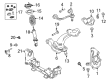
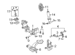
OEM 2009 Mercury Grand Marquis Control Arm
Suspension Arm- Select Vehicle by Model
- Select Vehicle by VIN
Select Vehicle by Model
orMake
Model
Year
Select Vehicle by VIN
For the most accurate results, select vehicle by your VIN (Vehicle Identification Number).
7 Control Arms found


2009 Mercury Grand Marquis Upper Control Arm, Front Driver Side Part Number: 6W1Z-3085-B
$92.93 MSRP: $152.91You Save: $59.98 (40%)Ships in 1 Business DayProduct Specifications- Other Name: Arm Assembly - Front Suspension; Front Left Upper Control Arm and Ball Joint Assembly.; Control Arm
- Manufacturer Note: L.H., Upper Control Arm only, stamped., FROM 12/05/05
- Position: Front Upper Driver Side
- Replaces: 6W1Z-3085-AA
- Base No.: 3084
- Item Weight: 6.10 Pounds
- Item Dimensions: 4.2 x 11.6 x 13.4 inches
- Condition: New
- Fitment Type: Direct Replacement
- SKU: 6W1Z-3085-B
- Warranty: This genuine part is guaranteed by Ford's factory warranty.

2009 Mercury Grand Marquis Upper Control Arm, Front Passenger Side Part Number: 6W1Z-3084-B
$92.93 MSRP: $152.91You Save: $59.98 (40%)Ships in 1-2 Business DaysProduct Specifications- Other Name: Arm Assembly - Front Suspension; Front Right Upper Control Arm and Ball Joint Assembly.; Control Arm
- Manufacturer Note: R.H., Upper Control Arm only, stamped., FROM 12/05/05
- Position: Front Upper Passenger Side
- Replaces: 6W1Z-3084-AA
- Base No.: 3084
- Item Weight: 5.50 Pounds
- Item Dimensions: 4.1 x 11.7 x 13.7 inches
- Condition: New
- Fitment Type: Direct Replacement
- SKU: 6W1Z-3084-B
- Warranty: This genuine part is guaranteed by Ford's factory warranty.


2009 Mercury Grand Marquis Lower Control Arm, Front Driver Side Part Number: 6W7Z-3079-B
$171.81 MSRP: $233.80You Save: $61.99 (27%)Product Specifications- Other Name: Arm Assembly - Front Suspension; Front Left Lower Control Arm and Ball Joint Assembly.; Control Arm
- Position: Front Lower Driver Side
- Base No.: 3078
- Item Weight: 27.40 Pounds
- Item Dimensions: 4.6 x 15.6 x 26.0 inches
- Condition: New
- Fitment Type: Direct Replacement
- SKU: 6W7Z-3079-B
- Warranty: This genuine part is guaranteed by Ford's factory warranty.
2009 Mercury Grand Marquis Upper Control Arm, Front Passenger Side Part Number: 6W1Z-3084-U
$89.73 MSRP: $147.64You Save: $57.91 (40%)Ships in 1-3 Business DaysProduct Specifications- Other Name: Arm Assembly - Front Suspension; Suspension Control Arm, Front Right Upper; Control Arm
- Position: Front Upper Passenger Side
- Replaces: 6W1Z-3084-R, 6W1Z-3084-T, 6W1Z-3084-S, MCSOE-35, 4W1Z-3084-RH, 5W1Z-3084-AA
- Item Weight: 8.20 Pounds
- Item Dimensions: 5.2 x 15.7 x 13.7 inches
- Condition: New
- Fitment Type: Direct Replacement
- SKU: 6W1Z-3084-U
- Warranty: This genuine part is guaranteed by Ford's factory warranty.

2009 Mercury Grand Marquis Lower Control Arm, Front Passenger Side Part Number: 6W1Z-3078-D
$226.54 MSRP: $341.82You Save: $115.28 (34%)Ships in 1-2 Business DaysProduct Specifications- Other Name: Arm Assembly - Front Suspension; Front Right Lower Control Arm and Ball Joint Assembly; Control Arm
- Manufacturer Note: R.H., standard suspension, without special packages, FROM 12/05/05
- Position: Front Lower Passenger Side
- Base No.: 3078
- Item Weight: 27.60 Pounds
- Item Dimensions: 5.2 x 15.6 x 26.3 inches
- Condition: New
- Fitment Type: Direct Replacement
- SKU: 6W1Z-3078-D
- Warranty: This genuine part is guaranteed by Ford's factory warranty.
 Product Specifications
- Other Name: Arm Assembly - Front Suspension; Front Right Lower Control Arm and Ball Joint Assembly; Control Arm
- Position: Front Lower Passenger Side
- Base No.: 3078
- Item Weight: 26.10 Pounds
- Item Dimensions: 4.7 x 15.7 x 26.3 inches
- Condition: New
- Fitment Type: Direct Replacement
- SKU: 6W7Z-3078-B
- Warranty: This genuine part is guaranteed by Ford's factory warranty.
- Product Specifications
- Other Name: Arm Assembly - Front Suspension; Front Left Lower Control Arm and Ball Joint Assembly.; Control Arm
- Manufacturer Note: L.H., standard suspension, without special packages, FROM 12/05/05
- Position: Front Lower Driver Side
- Base No.: 3078
- Item Weight: 26.30 Pounds
- Item Dimensions: 6.1 x 15.6 x 25.8 inches
- Condition: New
- Fitment Type: Direct Replacement
- SKU: 6W1Z-3079-D
- Warranty: This genuine part is guaranteed by Ford's factory warranty.
2009 Mercury Grand Marquis Control Arm
If you're seeking quality and affordability, look no further than our extensive inventory of genuine 2009 Mercury Grand Marquis Control Arm available at FordPartsDeal.com. You can confidently purchase our OEM 2009 Mercury Grand Marquis Control Arm as they are supported by the manufacturer's warranty and our hassle-free return policy, alongside the benefit of our fast delivery service.
2009 Mercury Grand Marquis Control Arm Parts Q&A
- Q: How to Service and Repair the Upper Control Arm on 2009 Mercury Grand Marquis?A: The first step when servicing or repairing the upper control arm involves measuring how far the wheel hub center lies from the fender lip while the vehicle remains stationary on level ground because this distance will guide reinstallation. A depowered fire suppression system must be ensured before beginning the operation to prevent serious injury. You should carefully detach the pivot bolt and flagnut on the right upper suspension arm-to-axle bracket without forcing it to prevent brake line damage. The mechanic should first remove the upper arm-to-axle bolt and flagnut before proceeding to remove the upper arm-to-frame bolt and the upper arm for replacement of the nut and bolt. When fitting the new upper arm users should observe the front and outboard markings to correctly position the rear suspension upper arms. You should place the new upper arm-to-frame bolt and the upper arm-to-axle bolt with flagnut in their positions yet loosely. A suitable jack should elevate the suspension until reaching the target distance is accomplished before tightening the upper arm-to-frame bolt to 150 Nm (111 lb-ft) and the upper arm-to-axle bolt to 90 Nm (66 lb-ft). Properties on the wheel and tire being installed next followed by a repowering of the fire suppression system according to safe procedure specifications.
Related 2009 Mercury Grand Marquis Parts
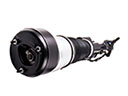 2009 Mercury Grand Marquis Air Suspension
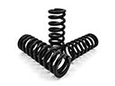 2009 Mercury Grand Marquis Coil Springs
 2009 Mercury Grand Marquis Air Suspension Solenoid
 2009 Mercury Grand Marquis Alignment Bolt
 2009 Mercury Grand Marquis Coil Spring Insulator
 2009 Mercury Grand Marquis Ride Height Sensor
 2009 Mercury Grand Marquis Shock And Strut Mount
 2009 Mercury Grand Marquis Steering Knuckle
 2009 Mercury Grand Marquis Sway Bar Bracket
 2009 Mercury Grand Marquis Sway Bar Kit
 2009 Mercury Grand Marquis Sway Bar Link
 2009 Mercury Grand Marquis Wheel Seal