FordParts
My Garage
My Account
Cart
OEM 2009 Mercury Mariner Clock Spring
Spiral Cable Clock Spring- Select Vehicle by Model
- Select Vehicle by VIN
Select Vehicle by Model
orMake
Model
Year
Select Vehicle by VIN
For the most accurate results, select vehicle by your VIN (Vehicle Identification Number).
1 Clock Spring found


2009 Mercury Mariner Clockspring Part Number: 8L8Z-14A664-A
$130.13 MSRP: $200.82You Save: $70.69 (36%)Ships in 1-3 Business DaysProduct Specifications- Other Name: Cover And Contact Plate Assembly; Air Bag Clockspring
- Base No.: 14A664
- Item Weight: 1.20 Pounds
- Item Dimensions: 14.1 x 7.1 x 5.2 inches
- Condition: New
- Fitment Type: Direct Replacement
- SKU: 8L8Z-14A664-A
- Warranty: This genuine part is guaranteed by Ford's factory warranty.
2009 Mercury Mariner Clock Spring
If you're seeking quality and affordability, look no further than our extensive inventory of genuine 2009 Mercury Mariner Clock Spring available at FordPartsDeal.com. You can confidently purchase our OEM 2009 Mercury Mariner Clock Spring as they are supported by the manufacturer's warranty and our hassle-free return policy, alongside the benefit of our fast delivery service.
2009 Mercury Mariner Clock Spring Parts Q&A
- Q: How to Service and Repair the Clock Spring Assembly on 2009 Mercury Mariner?A: In order to fix the Clock Spring assembly, shut the power of the SRS. Before removal of steering wheel, remove driver air bag module, tilt steering wheel, and straighten road wheels. Install the Clock Spring making sure that it is in the middle after which components are reattached and SRS is repowered.
Related 2009 Mercury Mariner Parts
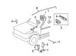
 2009 Mercury Mariner Air Bag
 2009 Mercury Mariner Air Bag Control Module
 2009 Mercury Mariner Air Bag Sensor
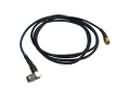 2009 Mercury Mariner Antenna Cable
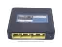 2009 Mercury Mariner Engine Control Module
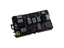 2009 Mercury Mariner Fuse
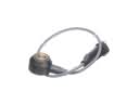 2009 Mercury Mariner Knock Sensor
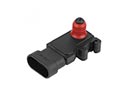 2009 Mercury Mariner MAP Sensor
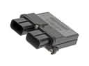 2009 Mercury Mariner Occupant Detection Sensor
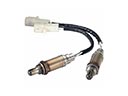 2009 Mercury Mariner Oxygen Sensors
 2009 Mercury Mariner Temperature Sender
 2009 Mercury Mariner Wiper Motor