FordParts
My Garage
My Account
Cart
OEM 2009 Mercury Mariner Shock Absorber
Suspension Shock Absorber- Select Vehicle by Model
- Select Vehicle by VIN
Select Vehicle by Model
orMake
Model
Year
Select Vehicle by VIN
For the most accurate results, select vehicle by your VIN (Vehicle Identification Number).
3 Shock Absorbers found


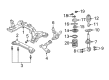
2009 Mercury Mariner Strut, Front Driver Side Part Number: 8L8Z-18124-BL
$102.56 MSRP: $172.18You Save: $69.62 (41%)Ships in 1-2 Business DaysProduct Specifications- Other Name: Shock Absorber Assembly - Front; Front Left Suspension Strut Kit; Complete Strut Set.; Shock Absorber
- Position: Front Driver Side
- Replaces: 6L8Z-18124-BB, 8L8Z-18124-AL, AST-229, 9L8Z-18124-AL, AST-303, 6L8Z-18124-AC, AST-227, 6T2Z-18124-AB, 9M6Z-18124-AL, AST-877, AST-226, 9L8Z-18124-BL, AST-876, AST-878
- Base No.: 18124
- Item Weight: 14.20 Pounds
- Item Dimensions: 32.2 x 7.5 x 7.6 inches
- Condition: New
- Fitment Type: Direct Replacement
- SKU: 8L8Z-18124-BL
- Warranty: This genuine part is guaranteed by Ford's factory warranty.


2009 Mercury Mariner Strut, Front Passenger Side Part Number: 8L8Z-18124-BR
$98.44 MSRP: $165.27You Save: $66.83 (41%)Ships in 1-2 Business DaysProduct Specifications- Other Name: Shock Absorber Assembly; Front Right Suspension Strut Kit; Complete Strut Set.; Shock Absorber
- Position: Front Passenger Side
- Replaces: 6L8Z-18124-AB, 6L8Z-18124-BA, 9L8Z-18124-AR, AST-225, AST-875, AST-230, 6T2Z-18124-AC, 8L8Z-18124-AR, 9L8Z-18124-BR, AST-880, 9M6Z-18124-AR, AST-879, AST-232, AST-305
- Base No.: 18124
- Item Weight: 15.20 Pounds
- Item Dimensions: 31.9 x 7.5 x 7.5 inches
- Condition: New
- Fitment Type: Direct Replacement
- SKU: 8L8Z-18124-BR
- Warranty: This genuine part is guaranteed by Ford's factory warranty.


2009 Mercury Mariner Shock Absorber, Rear Part Number: 8L8Z-18125-B
$63.87 MSRP: $105.09You Save: $41.22 (40%)Ships in 1-2 Business DaysProduct Specifications- Other Name: Shock Absorber Assembly; Rear Suspension Shock Absorber Kit; Complete Strut Assembly.; Shock; Suspension Shock Absorber
- Position: Rear
- Replaces: 8L8Z-18125-A, 9L8Z-18125-C, AST-312, ASH-1182, AST-310, ASH-1181, CL8Z-18125-A, ASH-1183, 7L8Z-18125-A, ASH-24510, 8L8Z-18125-D, ASH-24512, ASH-24511, 8L8Z-18125-C, CL8Z-18125-B, 9L8Z-18125-B, AST-309, CL8Z-18125-C
- Base No.: 18125
- Item Weight: 5.20 Pounds
- Item Dimensions: 31.1 x 3.4 x 3.4 inches
- Condition: New
- Fitment Type: Direct Replacement
- Require Quantity: 2
- SKU: 8L8Z-18125-B
- Warranty: This genuine part is guaranteed by Ford's factory warranty.
2009 Mercury Mariner Shock Absorber
If you're seeking quality and affordability, look no further than our extensive inventory of genuine 2009 Mercury Mariner Shock Absorber available at FordPartsDeal.com. You can confidently purchase our OEM 2009 Mercury Mariner Shock Absorber as they are supported by the manufacturer's warranty and our hassle-free return policy, alongside the benefit of our fast delivery service.
2009 Mercury Mariner Shock Absorber Parts Q&A
- Q: How to service the rear shock absorber on 2009 Mercury Mariner?A: The service procedure for the rear shock absorber begins with removing both the rear quarter trim panel and wheel and tire. A suitable jackstand should be used for supporting the rear suspension. You should first eliminate the upper shock absorber nut along with the bushing assembly then introduce fresh components by installing a nut with bushing followed by tightening it to 40 Nm (30 lb-ft). After removing the lower shock absorber nut with washer and bolt utilize a new nut which should be tightened to 175 Nm (129 lb-ft). Reinstall the shock absorber while performing the reverse order of removal to end the installation process. Maintenance success relies heavily on the use of equivalent quality new parts with identical part numbers followed by torquing each component to its specified values so that suspension components work correctly.
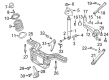
Related 2009 Mercury Mariner Parts
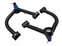 2009 Mercury Mariner Control Arm
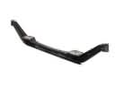 2009 Mercury Mariner Axle Beam
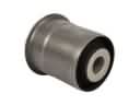 2009 Mercury Mariner Axle Support Bushings
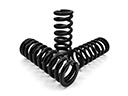 2009 Mercury Mariner Coil Springs
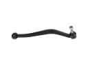 2009 Mercury Mariner Lateral Arm
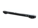 2009 Mercury Mariner Rear Crossmember
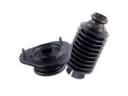 2009 Mercury Mariner Shock and Strut Boot
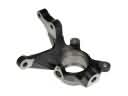 2009 Mercury Mariner Steering Knuckle
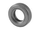 2009 Mercury Mariner Strut Bearing
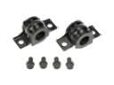 2009 Mercury Mariner Sway Bar Bracket
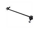 2009 Mercury Mariner Sway Bar Link
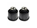 2009 Mercury Mariner Trailing Arm Bushing